
Front Panel I/O Connectivity Design Guide


Cabling Design Guidelines
39
4.4 USB Cabling (Motherboard to I/O Interface Board)
4.4.1 Introduction
This chapter provides some details of the design for a front panel USB 1.1 and 2.0 interface cable to
be used in conjunction with the front panel I/O interface board and main board. The interface cable
must be shielded as specified in Figure 14, for two reasons:
• To ensure the cable data lines meet the required differential characteristic impedance as given
in the most recent USB specification. Cables with an impedance variation outside of the USB
specification limits will degrade signal quality and could cause front panel USB devices to fail
to operate reliably.
• To shield the cable from RF emissions inside the chassis. Improperly shielded interface cables
can pick up these internally radiated signals and cause the system to fail EMI testing.
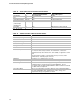
Figure 14, Figure 15 and Figure 16 shows the recommended USB interface cable shielding details
and pin assignments. Pin assignments are further detailed in Table 16. The cable materials
(including connectors) and construction should enable the system to meet the performance
requirements of the most current USB 2.0 Specification and applicable safety and regulatory
requirements.
Table 17 and Table 20 show some current recommendations regarding cable parts and materials.
The cable length (in combination with the trace lengths on the main board and front panel I/O
interface board) must be such that it will satisfy the signal quality requirements (propagation delay,
etc.) given in the most recent version of the USB 2.0 Specification.
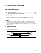
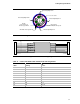
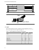
4.4.2 Cable Drawings
Twisted Signaling Pair A:
White: USB_FP_P0-
Green: USB_FP_P0+
Twisted Signaling Pair B:
White: USB_FP_P1-
Green: USB_FP_P1+
Cover Jacket
Inner Shield:
Aluminum Metalized Polyester
Non-Twisted:
Red: VREG_FP_USBPWR0
Non-Twisted:
Black: GROUND
Outer Shield:
> 65% Interwoven
Tinned Copper Braid
Figure 14. Dual Port USB Cable Cross Section