
Front Panel I/O Connectivity Design Guide


Front Panel I/O Connectivity Design Guide
40
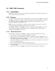
KEY
Signal
20
20
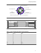
VREG_FP_USBPWR0
GROUND
28
28
USB_FP_P1-
USB_FP_P1+
28
28
USB_FP_P0-
USB_FP_P0+
AWG
3
8
1
6
4
5
P1
10
7
7
7
7
9
P2
3
8
1
6
4
5
10
7
7
7
7
9KEY
A
B
2 2Unused Unused
GROUND (Shield)N/A
Twisted Pair
KEY
KEY
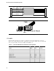
Figure 15. Dual Port USB Cable Wiring Diagram
1
210
9
KEY
19
10
2
Cable
Key for Shroud
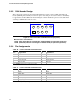
Figure 16. Dual USB Cable Diagram
NOTE
Shrouded stake pin headers are highly recommended. An un-shrouded header is shown in
Figure 16 to clearly illustrate the pin configuration of the header. Cable connectors P1 should
mate to header numbered as shown in Table 16 and Table 17.
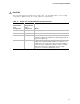
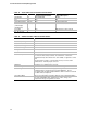
Table 16. Dual Port USB Cable and Connector Pin Assignments
Signal AWG Color
PIN
P1 / P2
VREG_FP_USBPWR 20 Red 1 / 1
VREG_FP_USBPWR 20 Red 2 / 2
USB_FP_P0- 28 White 3 / 3
USB_FP_P1- 28 White 4 / 4
USB_FP_P0+ 28 Green 5 / 5
USB_FP_P1+ 28 Green 6 / 6
GROUND (Shield) N/A N/A 7 / 7
GROUND 20 Black 8 / 8
KEY N/A N/A 9 / 9
KEY N/A N/A 10 / 10