
Intel Desktop Board DG41MJ Technical Product Specification

Technical Reference
43
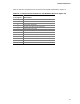
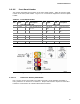
Table 16. Front Panel Audio Header for Intel
®
HD Audio
Pin Signal Name Pin Signal Name
1 [Port 1] Left channel 2 Ground
3 [Port 1] Right channel 4 PRESENCE# (Dongle present)
5 [Port 2] Right channel 6 [Port 1] SENSE_RETURN
7 SENSE_SEND (Jack detection) 8 Key (no pin)
9 [Port 2] Left channel 10 [Port 2] SENSE_RETURN
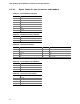
Table 17. Front Panel Audio Header for AC ’97 Audio
Pin Signal Name Pin Signal Name
1 MIC 2 AUD_GND
3 MIC_BIAS 4 AUD_GND
5 FP_OUT_R 6 FP_RETURN_R
7 AUD_5V 8 KEY (no pin)
9 FP_OUT_L 10 FP_RETURN_L
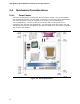
2.2.2.2 Add-in Card Connectors
The board has the following add-in card connectors:
• PCI Conventional (rev 2.3 compliant) bus: one PCI Conventional bus add-in card
connector.
Note the following considerations for the PCI Conventional bus connector:
• The PCI Conventional bus connector is bus master capable.
• SMBus signals are routed to the PCI Conventional bus connector. This enables PCI
Conventional bus add-in boards with SMBus support to access sensor data on the
board. The specific SMBus signals are as follows:
⎯ The SMBus clock line is connected to pin A40.
⎯ The SMBus data line is connected to pin A41.
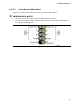
2.2.2.3 Auxiliary Front Panel Power/Sleep LED Header
Pins 1 and 3 of this header duplicate the signals on pins 2 and 4 of the front panel
header.
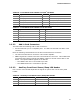
Table 18. Auxiliary Front Panel Power/Sleep LED Header
Pin Signal Name In/Out Description
1 HDR_BLNK_GRN Out Front panel green LED
2 Not connected
3 HDR_BLNK_YEL Out Front panel yellow LED