
microATX Motherboard Interface Specification

microATX Motherboard Interface Specification
Version 1.2
Page 10
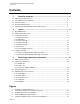
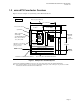
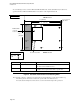
To avoid damage to traces on microATX and ATX motherboards, chassis standoffs in any locations not
specified for microATX and ATX should be removable or not be implemented at all.
ABC
F
GH J
K
LM
SR
New for microATX
9.6” (244 mm)
REAR of board
FRONT of board
NOT TO SCALE
12” (305 mm)
9.6”
(244 mm)
6.25” wide rear
I/O shield
PCI/ISA/AGP
connector
locations (4 max)
Key, mounting holes
ATX
microATX
Form factor Mounting hole locations Notes
microATX B, C, F, H, J, L, M, R, S Holes R and S are added for microATX form factor.
Hole B was defined in Full AT format
ATX A, C, F, G, H, J, K, L, M Hole F must be implemented in all ATX 2.1-compliant chassis
assemblies. It was optional in the ATX 1.1 specification.
Figure 2: microATX and ATX Form-factor Mounting Holes
Notes: In Figure 2, Figure 3, and Figure 8, the board is shown oriented with the rear of the board toward the top.
The shaded portion to the left above indicates the greater width of the ATX form factor.
For details about mounting holes and board sizes, see the mechanical drawing in this specification.