
microATX Motherboard Interface Specification

microATX Motherboard Interface Specification
Version 1.2
Page 11
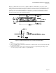
2.3 Connector Placement
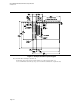
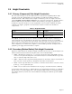
Table 5 lists connector locations. Figure 3 clearly defines the location of the PCI, ISA, and AGP connectors
as well as the allowable placement area for I/O connectors on the back panel. The specification provides
recommendations, but the exact location of other connectors is left to the judgment of the motherboard
designer working in conjunction with the system integrator.
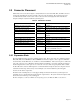
Table 5: Connector Locations
Feature Status Comment
Expansion slot connector locations Required See Figure 3.
Power input connector location Recommended Along the right-hand side of the board in Figure 3.
2x2 Processor power connector Required Next to the processor voltage regulation circuitry
Power input connector pinout Required See Figure 8.
Optional power connector pinout Not required See Figure 10 (as reference material for ATX 2. 1
or higher).
Disk I/O connector location Recommended Front edge of board, near drive bays.
Front panel I/O connector locations Recommended Front edge of board, right of expansion slots.
Back panel I/O panel size and location Required See Figure 4.
Back panel I/O connector zone Recommended See Figure 5.
Back panel I/O connector arrangement Optional See Figure 6 for an example.
Memory module connector location Recommended Between processor and expansion slots, or between
processor and disk I/O connectors.
Processor location Recommended Right of expansion slots, in front of back panel I/O
connectors.
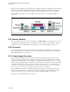
2.3.1 Expansion Slots
The microATX form-factor supports up to four expansion slots. These slots can be any combination of ISA,
PCI, CNR, AGP, shared ISA/PCI, or shared CNR/PCI add-in boards. Figure 3 shows a typical combination
of two ISA slots and two PCI slots, one of which is a shared ISA/PCI slot. The location of pin 1 is defined for
each of the connectors. If a combination other than that shown in Figure 3 is desired, motherboard designers
should extrapolate the location of pin one on each of the connectors. The slot spacing must remain constant.
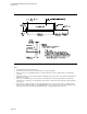
To allow all add-in cards to be full length, it is recommended that the height of any board component located
toward the front left edge of the board (as viewed in Figure 3) be less than 0.6 inches (15.2mm) (plus
clearance for the board components).
In addition to the mounting holes, for extra support during add-in board insertion the system designer can
optionally choose to add mechanical support under the expansion slots. The system and board designers must
decide the location and shape of any such support.
For more examples, see the microATX System Design Suggestions; for Web site URL, see Section 1.1.