
microATX Motherboard Interface Specification

microATX Motherboard Interface Specification
Version 1.2
Page 14
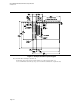
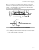
Figure 4: Chassis I/O Aperture Requirements
Notes:
• Datum B 0,0 = mounting location hole B.
• Nominal cutout size = 6.25 inches (158.75mm) by 1.75 inches (44.45mm).
• Distance from top of a typical 0.062 inches (1.57 mm) motherboard to bottom of I/O cutout hole = 0.150 inches
(3.81mm).
• Allowable thickness of a chassis back panel that the I/O shield can clip into is in the range 0.037 inches (0.94mm) to
0.052 inches (1.32mm).
• The corners of the I/O aperture can be rounded to a maximum radius of .039 inches (0.99mm). This allowable
rounding of the corners helps case manufacturers extend the life of their hard tooling while still complying with the
specification.
• The 0.1 inches (2.54mm) keepout zone around the I/O aperture area is required in an ATX 2.1-compliant chassis.
This allows microATX- and ATX 2.1-compliant I/O shields to fit into previous versions of ATX-compliant chassis.
The keepout area is needed for the shield attachment points. Avoid paint application in this area.