
microATX Motherboard Interface Specification

microATX Motherboard Interface Specification
Version 1.2
Page 15
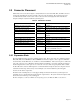
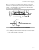
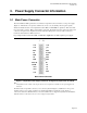
Figure 5 specifies the I/O connector zone. Compliance with this recommendation is necessary to ensure
enough clearance between the chassis aperture and motherboard connectors for the I/O shield structure. If the
shield provided with the motherboard requires less than the recommended clearance, then the dimensions of
the I/O connector area can be waived (hatched area in Figure 5: 5.990 inches [152.15mm] by 1.470 inches
[37.34mm]). To retain maximum flexibility, the exact positioning of connectors within the I/O connector
zone is left to the discretion of the motherboard designer.
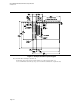
Figure 5: Motherboard I/O Connector Location Recommendation
Notes:
• Datum B 0,0 = mounting location hole B.
• The face of all I/O connectors should be placed 0.445 inches (11.30mm) from the reference datum and remain within
the zone defined in Figure 5.
• The I/O aperture should be a simple cutout of the chassis back panel. Recessing the I/O aperture will prevent the
case from accepting microATX- and ATX 2.1-compliant I/O shields.