
microATX Motherboard Interface Specification

microATX Motherboard Interface Specification
Version 1.2
Page 16
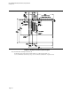
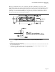
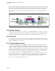
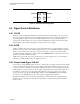
Figure 6 shows an example of rear panel I/O connector layout, featuring stacked keyboard and mouse, stacked
USB ports, stacked serial and parallel and VGA ports, a LAN port, and stacked audio jacks. This layout is
only an example—the microATX form factor allows complete flexibility in the layout of rear panel I/O.
For more I/O panel examples, see the microATX System Design Suggestions; for the Web site URL, see
Section 1.1.
Figure 6: Example Rear Panel I/O Connector Layout
2.3.5 Memory Sockets
The exact location of the memory sockets, whether they are SIMM, DIMM, or some other type of connector,
is not rigidly specified. It is the designer’s responsibility to meet the keepout zone requirements. For more
information, see the microATX Motherboard Design Suggestions; for Web site URL, see Section 1.1.
2.3.6 Processor
The exact location of the processor is not specified. It is the designer’s responsibility to meet the keepout
zone requirements. For more information, see the microATX Motherboard Design Suggestions; for Web site
URL and availability date, see Section 1.1.
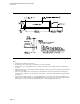
2.3.7 Power Supply Connector
The microATX power supply connector definition is identical to that of ATX. The exact location of the
power connector is not specified. It is recommended that it be placed along the right-hand side of the board
(“right” per orientation of board as shown in Figure 3), considering the location of the processor, core logic,
and clearance for the peripheral bays. Locating the 2x2 processor power connector near the processor voltage
regulation circuitry will help to ensure clean power and improve board layout. It is recommended that the
power plane connected to the 2 x 2 should not be the same power plane as the one connected to the main
power connector (2 x 12) as power on the plane has the potential to exceed 240 VA.
The microATX system designer can use small form-factor power supplies or the standard ATX 2.1 power
supply. For more information, see the SFX12V Power Supply Design Guide and the TFX12V (Thin Form
Factor with 12-V Connector) Power Supply Design Guide; for the Web site URL, see Section 1.1.
For power connector signal definitions, see Section 3.