
microATX Motherboard Interface Specification

microATX Motherboard Interface Specification
Version 1.2
Page 18
(9.600)
[243.84]
(9.600)
[243.84]
AREA B
AREA A
AREA C
REF (BOARD MTG HOLE)1.350
[34.29]
REF
(BOARD MTG HOLE)
.400
[10.16]
2.050
[52.07]
3.750
[95.25]
8.250
[209.55]
6.100
[154.94]
7.100
[180.34]
9.200
[233.68]
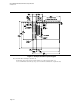
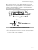
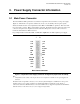
Area Maximum component height (in inches)
A Motherboard component height, 2.80 inches [71.12mm] maximum
Chassis clearance over motherboard, 3.0 inches [76.20mm] required
Chassis clearance over motherboard, 3.5 inches [88.90mm] recommended
B 0.60 inches [15.24mm] (expansion slot area)
C 1.50 inches [38.10mm] (see Notes)
Figure 7: microATX Motherboard Maximum Component Height Restrictions
Notes:
• Datum B 0,0 = mounting location hole B.
• The component height requirement assumes a motherboard thickness of 0.062” (1.57 mm). The maximum height
specified for Area C is intended to avoid interference between motherboard components and the chassis structure
and to provide backward-compatibility with microATX 1.0 or higher.
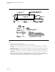
• When designing a microATX motherboard, attention should also be paid to keepouts specific to the specifications
for the type of add-in card slots being integrated into the motherboard, which may have additional requirements for
motherboard component heights. Examples of this are the PCI and AGP add-in card specifications which require a
maximum component height in the area between the card connector and the rear panel that is less than the Area B
component heights.