
microATX Motherboard Interface Specification

microATX Motherboard Interface Specification
Version 1.2
Page 19
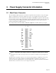
3. Power Supply Connector Information
3.1 Main Power Connector
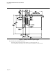
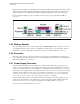
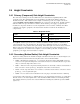
The microATX and ATX specifications recommend a 24-pin main connector interface to the power supply
(Figure 8). This interface incorporates standard
±5V, ±12V, 3.3V, 5V standby, and soft-power signals.
This board-mounted header can be implemented with a Molex* 44206-0007 or equivalent. This mates with
the power supply connector, Molex 39-01-2240 or equivalent. All signals and power rails on the main power
connector are required to be implemented for the main microATX power connector. This connector is
identical to that defined for ATX Version 2.2.
Proper implementation of PS-ON, 5VSB, and PW-OK is required for an ATX-compliant power supply.
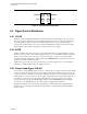
Figure 8: 20-pin Main Power Supply Connector Configuration (required for microATX)
Note:
* All signals that can be carried on the 24-pin connector are not required or available on some power supplies.2x2
Connector
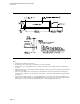
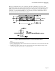
In addition to the 24-pin main connector, a 2x2 connector (shown in Figure 9) is utilized for +12 V power
signals for the processor voltage regulator. For detailed information regarding the power supply or
connectors for the microATX form factor, refer to the SFX12V Power Supply Design Guide or the TFX12V
(Thin Form Factor with 12 V Connector) Power Supply Design Guide.
1
1
+3.3
+3.3
+3.3
-
12V
CO
CO
+5V PS_O
CO
CO
+5V
CO
CO
CO
PWR_ N
+5V
+5V
+12V
+5V
+12V
+5V
+3.3V
CO
Main Power Connector
1
13
+3.3V +3.3V
+3.3V
-
12V
COM COM
+5V
PS_ON#
COM
COM
+5V COM
COM
COM
PWR_ON NC
+5VSB
+5V
+12V1
+5V
+12V1
+5V
+3.3V
COM
Main Power Connector