
microATX Motherboard Interface Specification

microATX Motherboard Interface Specification
Version 1.2
Page 7
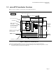
1.2 microATX Form-factor Overview
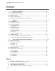
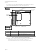
Figure 1 shows an example of a system using a microATX motherboard.
9.6”
FRONT
of board
REAR of board
(244 mm)
PCI, ISA, or AGP add-in board slots
Not to scale
Processor location
Fan
5.25” drive bay
for CD-ROM
9.6” x 9.6” (244 x 244 mm) motherboard
9.6” (244 mm)
3.5” drive bay
for FDD
Power supply
location
Expansion slot #5
Expansion slot #6
Expansion slot #4
Expansion slot #7
ATX-compatible
double-high
expandable I/O window
6.25” (158.75 mm)
x
1.75” (44.45 mm)
Alternate power supply
and fan location
(over processor)
Slots for system memory
H
D
D
b
a
y
IDE, FDD,
and front
panel
connectors
P
O
W
E
R
System Fan
Figure 1: Example of a microATX System
(oriented for example installation in a tower, side view; front of board to the right in this figure)
Note: The example in Figure 1 shows expansion slot numbers 4 through 7. Slots 1 through 3 are present on an ATX
motherboard, which is wider than a microATX board.