
Plug and Play BIOS Specification


Plug and Play BIOS Specification 1.0A Page 18
dependent upon the Base-Type code. The third byte defines the specific device programming interface,
IF.-Type, based on the Base-Type and Sub-Type.
Refer to Appendix B for a description of Device Type Codes.
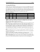
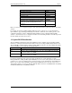
Device Indicators - This field contains indicator bits that identify the device as being capable of being
one of the three identified boot devices: Input, Output, or Initial Program Load (IPL).
Bit Description
7 A 1 indicates that this ROM supports the Device Driver Initialization Model
6 A 1 indicates that this ROM may be Shadowed in RAM
5 A 1 indicates that this ROM is Read Cacheable
4 A 1 indicates that this option ROM is only required if this device is selected as a boot
device.
3 Reserved (0)
2 A 1 in this position indicates that this device is an Initial Program Load (IPL) device.
1 A 1 in this position indicates that this device is an Input device.
0 A 1 in this position indicates that this device is a Display device.
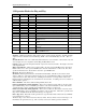
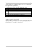
Boot Connection Vector (Real/Protected mode) - This location contains an offset from the start of the
option ROM header to a routine that will cause the Option ROM to hook one or more of the primary
input, primary display, or Initial Program Load (IPL) device vectors (INT 9h, INT 10h, or INT 13h),
depending upon the parameters passed during the call.
When the system BIOS has determined that the device controlled by this Option ROM will be one of the
boot devices (the Primary Input, Primary Display, or IPL device), the System ROM will execute a FAR
CALL to the location pointed to by the Boot Connection Vector. The system ROM will pass the
following parameters to the options ROM's Boot Connection Vector: