
Plug and Play BIOS Specification

Plug and Play BIOS Specification 1.0A Page 21
Upon exit from the initialization call, Plug and Play Option ROMs should return some boot device status
information in the following format:
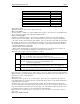
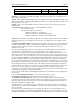
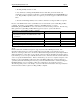
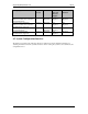
Return Status from Initialization Call:
AX Bit Description
8 1 = IPL Device supports INT 13h Block Device format
7 1 = Output Device supports INT 10h Character Output
6 1 = Input Device supports INT 9h Character Input
5:4 00 = No IPL device attached
01 = Unknown whether or not an IPL device is attached
10 = IPL device attached
(RPL devices have a connection).
11 = Reserved
3:2 00 = No Display device attached
01 = Unknown whether or not a Display device is attached
10 = Display device attached
11 = Reserved
1:0 00 = No Input device attached
01 = Unknown whether or not an Input device is attached
10 = Input device attached
11 = Reserved
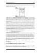
3.4 Option ROM Initialization flow
The following outlines the typical steps used to initialize Option ROMs during a Plug and Play system
BIOS POST:
Step 1 Initialize the boot device option ROMs.
This includes the Primary Input, Primary Output, and Initial Program Load (IPL) device option
ROMs.
Step 2 Initialize ISA option ROMs by performing ISA ROM scan
The ISA ROM scan should be performed from C0000h to EFFFFh on every 2k boundary. Plug
and Play option ROMs will not be included in the ROM scan.
Step 3 Initialize option ROMs for ISA devices which have a Plug and Play option ROM.
Typically, these devices will not provide support for dynamic configurability. However, the
resources utilized by these devices can be obtained through the Static Resource Information
Vector as described in section 3.2.
Step 4 Initialize option ROMs for Plug and Play cards which have a Plug and Play option ROM.
Step 5 Initialize option ROMs which support the Device Driver Initialization Model (DDIM).
Option ROMs which follow this model make the most efficient use of space consumed by option
ROMs. Refer to Appendix B for more information on the DDIM.
3.5 ISA Option ROMs and Resource Mapping
Given the fact that add-in cards are encouraged to make all of their resource assignments flexible, there
arises an interesting issue for Option ROMs, in how does the Option ROM code "know" which resource
values to use to communicate with the card? There are several possible solutions to this problem, but the
one selected for Plug and Play Option ROMs is as follows.
When the Plug and Play Option ROM is initialized, it will be passed the CSN and Read Data Port. The
Option ROM can use this information to determine which resources were assigned to it. When the Option
ROM has determined this, it should then setup its entry vectors based upon the resource assignment. For
example, if an add-in SCSI controller has two possible I/O Port assignments, 300h and 310h, then it
should have two different entry vectors for INT 13h. Depending upon which base I/O address is assigned,
the Option ROM will setup the INT 13h vector to point to the proper entry vector. Thereafter, whenever