
Plug and Play BIOS Specification

Plug and Play BIOS Specification 1.0A Page 26
be a static device, which means it is not configurable. If the information is provided in this descriptor
block and in a configuration file, the possible resource selections must be specified in the same order that
they are described in the configuration file. If the node does not contain the alternative resource selections
then the first byte in this block will contain the End Tag descriptor, which is described in Plug and Play
ISA Specification, to indicate that there are no resources in this block.
Compatible device identifiers:
The compatible device identifiers block specifies the IDs of other devices that this device is compatible
with. System software can use this information to load compatible device drivers if necessary. The format
of the data contained in this block follows the format defined in the Plug and Play ISA Specification
under the section labeled Plug and Play Resources - Compatible Device ID.
4.3 Plug and Play BIOS Functions
The following subsections describe the Plug and Play BIOS interface. The function return values are
listed in Appendix C. The Plug and Play BIOS functions will preserve all FLAGS and registers
except for the AX register, which will contain the return code. The BIOS functions will use the
caller's stack and a minimum of 1024 bytes of stack space must be available to these functions. It is
important to note that system BIOS function(s) used to set the configuration of a systemboard device
will not validate the configuration information passed by the caller and may not return an error
code.
Option ROM initialization routines can not depend on any of the Plug and Play runtime functions to be
available until after INT19 has been invoked at the end of the POST process.
4.4 Plug and Play Installation Check
This section describes the method for system software to determine if the system has a Plug and Play
BIOS. This Plug and Play installation check indicates whether the system BIOS support for accessing the
configuration information about the devices on the systemboard is present and the entry point to these
BIOS functions. This method involves searching for a signature of the ASCII string $PnP in system
memory starting from F0000h to FFFFFh at every 16 byte boundary. This signature indicates the system
may have aPlug and Play BIOS and identifies the start of a structure that specifies the entry point of the
BIOS code which implements the support described in this document. The system software can determine
if the structure is valid by performing a Checksum operation.
The method for calculating the checksum is to add up Length bytes from the top of the structure, including
the Checksum field, into an 8-bit value. A resulting sum of zero indicates a valid checksum operation.
The entry points specified in this structure are the software interface to the BIOS functions. The structure
element that specifies the 16-bit protected mode entry point will allow the caller to construct a protected
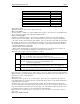
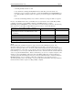
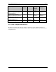
mode selector for calling this support. The structure of the Plug and Play BIOS Support Installation
Check is as follows:
Field Offset Length Value
Signature 00h 4 BYTES $PnP (ASCII)
Version 04h BYTE 10h
Length 05h BYTE 21h
Control field 06h WORD Varies
Checksum 08h BYTE Varies
Event notification flag address 09h DWORD Varies
Real Mode 16-bit offset to entry point 0Dh WORD Varies
Real Mode 16-bit code segment address 0Fh WORD Varies
16-Bit Protected Mode offset to entry point 11h WORD Varies
16-Bit Protected Mode code segment base
address
13h DWORD Varies