
Plug and Play BIOS Specification

Plug and Play BIOS Specification 1.0A Page 27
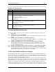
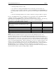
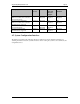
OEM Device Identifier 17h DWORD Varies
Real Mode 16-bit data segment address 1Bh WORD Varies
16-Bit Protected Mode data segment base address 1Dh DWORD Varies
Signature is represented as the ASCII string "$PnP", where byte 0='$' (24h), byte 1='P' (50h),byte 2='n'
(6Eh), and byte 3='P' (50h).
Version - This is a BCD value that implies a level of compliance with major (high nibble) and minor (low
nibble) version changes of the Plug and Play BIOS specification. For example, the BCD value 10h would
be interpreted as version 1.0.
Length - Length of the entire Installation Structure expressed in bytes. The length count starts at the
Signature field.
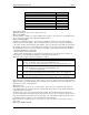
The Control field is a bit-field that provides system capabilities information.
bits 15:2: Reserved (0)
bits 1:0: Event notification mechanism
00=Event notification is not supported
01=Event notification is handled through polling
10=Event notification is asynchronous (at interrupt time)
Checksum - The method for calculating the checksum is to add up the number of bytes in the Installation
Structure, including the Checksum field, into an 8-bit value. A resulting sum of zero indicates a valid
checksum.
The Event notification flag address specifies the physical address of the Event Flag if event notification
is handled through polling. When event notification is handled through polling, bit 0 of the Event Flag
will be set when a system event occurs. System software will monitor or poll the Event Flag for
notification of an event.
If events are handled through asynchronous notification, the system BIOS will specify a system device
node which can be obtained from the Get Node runtime function. The system device node for
asynchronous event management will be identified through the device identifier field in the device node
data structure and will specify the IRQ number and an I/O port address. This event system device node
can be defined in one of two ways. First, the device node can follow the generic implementation in which
the device identifier is PNP0C03, and the interrupt number and I/O address assigned are system specific.
The only requirement with the generic implementation is that the I/O address bit used for detecting the
source of the interrupt and clearing the interrupt line is bit 0. If bit 0 of this I/O address is set to 1, then
the interrupt was generated due to a system event. The interrupt service routine should reset the interrupt
line by clearing bit 0 at the specified I/O address. All other bits read from the I/O address should not be
modified. The second way the event system device node can be defined is implementation specific where
the system vendor must supply their own device identifier and whatever resources are required for
servicing the event interrupt. This method will require a specific device driver associated with the device
node identifier to support the event notification interface.
System software should check the Control field to determine the event notification method implemented
on the system.
Refer to the Event Notification Interface section for more information on events.
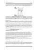
The Real Mode 16-Bit interface is basically the segment:offset of the entry point.
The 16-Bit Protected Mode interface specifies the code segment base address so that the caller can
construct the descriptor from this segment base address before calling this support from protected mode.
The offset value is the offset of the entry point. It is assumed that the 16-Bit Protected Mode interface is
sufficient for 32-Bit Protected Mode callers.
The caller must also construct data descriptors for the functions that return information in the function
arguments that are pointers. The only limitation is that the pointer offset can only point to the first 64K
bytes of a segment.
If a call is made to these BIOS functions from 32-bit Protected Mode, the 32-bit stack will be used for
passing any stack arguments to the Plug and Play BIOS functions. However, it is important to note that
the Plug and Play BIOS functions are not implemented as a full 32-bit protected mode interface and will