
Plug and Play BIOS Specification

Plug and Play BIOS Specification 1.0A Page 32
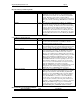
unsigned int Control; /* Control Flag */
unsigned int BiosSelector; /* PnP BIOS readable/writable selector */
Description:
Required. This function will copy the information for the specified System Device Node into the buffer
specified by the caller. The Node argument is a pointer to the unique node number (handle). If Node
contains 0, the system BIOS will return the first System Device Node. The devNodeBuffer argument
contains the pointer to the caller's memory buffer. On return, Node will be updated with the next node
number, or if there are no more nodes, it will contain FFh. The System Device Node data will be placed
in the specified memory buffer.
The Control flag provides a mechanism for allowing the system software to request a node that indicates
either how the specified systemboard device is currently configured or how it is configured for the next
boot. Control is defined as:
Bits 15:2: Reserved (0)
Bit 1: 0=Do not get the information for how the device will be configured for the next boot.
1=Get the device configuration for the next boot (static configuration).
Bit 0: 0=Do not get the information for how the device is configured right now.
1=Get the information for how the device is configured right now.
If Control flag is 0, neither bit 0 nor bit 1 is set, or if both bits are set, this function should return
BAD_PARAMETER.
The BiosSelector parameter enables the system BIOS, if necessary, to update system variables that are
contained in the system BIOS memory space. If this function is called from protected mode, the caller
must create a data segment descriptor using the 16-bit Protected Mode data segment base address
specified in the Plug and Play Installation Check data structure, a limit of 64KB, and the descriptor must
be read/write capable. If this function is called from real mode, BiosSelector should be set to the Real
Mode 16-bit data segment address as specified in the Plug and Play Installation Check structure. Refer to
section 4.4 above for more information on the Plug and Play Installation Check Structure and the
elements that make up the structure.
The function is available in real mode and 16-bit protected mode.
Returns:
0 if successful - SUCCESS
!0 if an error (Bit 7 set) or a warning occurred - error code (The function return codes are described in
Appendix C)
The FLAGS and registers will be preserved, except for AX which contains the return code.
Example:
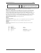
The following example illustrates how the 'C' style call interface could be made from an assembly
language module:
.
.
.
push Bios Selector
push Control Flag
push segment/selector of devNodeBuffer ; pointer to devNodeBuffer
push offset of devNodeBuffer
push segment/selector of Node ; pointer to Node number
push offset of Node
push GET_DEVICE_NODE ; Function 1
call FAR PTR entryPoint
add sp,14 ; Clean up stack
cmp ax,SUCCESS ; Function completed successfully?
jne error ; No-handle error condition
.
.
.