
Plug and Play BIOS Specification

Plug and Play BIOS Specification 1.0A Page 48
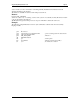
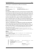
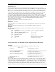
Example:
The following example illustrates how the 'C' style call interface could be made from an assembly
language module:
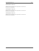
.
push Bios Selector
push segment/selector of the Resource Block ; Pointer to the data struct of isa resources
push offset of Resource Block
push GET_STATICALLY_ALLOCATED_RESOURCES ; Function 0Ah
call FAR PTR entryPoint
add sp,8 ; Clean up stack
cmp ax,SUCCESS ; Function completed successfully?
jne error ; No-handle error condition
.
4.7.3 Function 40h - Get Plug & Play ISA Configuration Structure
Synopsis:
int FAR (*entryPoint)(Function, Configuration, BiosSelector);
int Function; /* PnP BIOS Function 40h */
unsigned char FAR *Configuration; /* Address of caller's config. structure buffer*/
unsigned int BiosSelector; /* PnP BIOS readable/writable selector */
Description:
Required. This function is used to get the Plug and Play ISA Configuration structure. The Plug and Play
ISA Configuration data structure contains configuration information specific to ISA Plug and Play
support. This function will copy the data structure to the caller's memory buffer specified by
Configuration. A system without any ISA bus capabilities will return the
FUNCTION_NOT_SUPPORTED error code. When the ISA bus is present, the fields in this data
structure will be set with the appropriate values. If the system BIOS did not identify any Plug and Play
ISA cards in the system during POST, then the Total number of Card Select Numbers field will be zero
and the value in the ISA Read Data Port field is invalid and must not be used by system software.
On systems with a dynamic ISA bus, like portables, function 40h will be more flexible. When an ISA bus
is present, the information returned by function 40h will always be valid after a cold boot. On a cold boot
with no ISA bus present, function 40h will return zeros. After an ISA warm/hot dock, the function 40h
information will also be valid, if the plug and play BIOS isolates and enumerates the plug and play
adapter cards before returning control to the plug and play operating system. If the BIOS does not re-
enumerate after an ISA warm/hot dock event, then the information returned by function 40h will be zeros.
After an ISA undock event, this information will also be zeros.
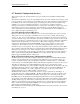
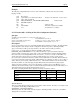
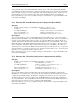
The format of the Plug and Play ISA Configuration structure is defined as follows:
Field Offset Length Value
Structure Revision 00h BYTE 01
Total number of Card Select Numbers (CSNs)
assigned
01h BYTE Varies
ISA Read Data Port 02h WORD Varies
Reserved 04h WORD 0
Structure Revision:
This is an ordinal value that indicates the revision number of this structure only and does not imply a level
of compliance with the Plug and Play BIOS version.
Total number of Card Select Numbers:
This field specifies the total number of CSNs assigned to ISA Plug and Play cards by the system BIOS
during the Power-On Self Test (POST).