
Accelerated Graphics Port Interface Specification


AGP3.0 Interface Specification
Rev. 1.0
22
dynamic calibration approaches can be utilized. In a static approach, the design accommodates, up
front, the worst-case changes within the three variables.
A dynamic calibration approach will adjust the parameters as changes in the variables occur. Process
variations need only be adjusted once. Voltage and temperature, however, will change during operation
and any buffer characteristic change beyond specification must be adjusted dynamically. (Dynamic
adjustment can also keep the buffers closer to the target specifications and improve timing and signal
integrity.) In order for dynamic adjustments to occur, the interface must enter a quiescent state when
there is no risk of corrupting an ongoing transaction. AGP3.0 provides a scheme called the calibration
cycle that can be used for dynamic adjustment (or compensation) of the key specification parameters.
The core-logic enables the bus calibration cycle only in the AGP3.0 mode of operation. The calibration
cycle is disabled when operating in AGP2.0 mode (1.5V signaling). The compensation scheme itself is
implementation specific and is beyond the scope of this document.
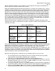
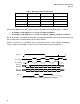
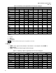
Only the high-speed source synchronous AGP signals need dynamic calibration. Most other slower
“common-clock” signals are calibrated once on power-up while a few don’t need any adjustments. Table
7 describes this further.
Table 7: Signal Calibrations
Signals Type Core-Logic
(Target)
Graphics Chip
(Master)
SBA#, SBA
Strobes
SBA Source
Synchronous
Uni-directional Type
Receiver Only
Needs termination
adjustment
Driver Only
Needs signal swing
and slew rate
adjustment
AD, C#/BE, AD
Strobes, DBI_HI,
DBI_LO
AD GROUP Source
Synchronous Bi-
Directional
Needs termination,
swing & slew rate
adjustments
Needs termination,
swing & slew rate
adjustments
ST[2:0], IRDY,
TRDY, FRAME,
GNT, DEVSEL,
STOP, REQ, etc.
Common Clock
Group
Slow enough that
one adjustment on
power up is
sufficient.
Same as Core-Logic
CLK, INT#, RST#
etc.
Misc. No adjustments No adjustments
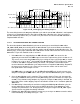
Since the AD signal group is bi-directional, an explicit bus event is needed to allow driver and termination
update to occur. AGP3.0 defines a calibration cycle that facilitates this activity. The calibration cycle is
initiated by the core-logic on a periodic basis. The period for this event is determined by the
programmed value in field PCAL_CYCLE of the core logic’s AGPCMD register (see section 2.7.5.). The
core-logic sets PCAL_CYCLE with a conservative default value. This default period can be changed by
configuration software based on the actual requirements advertised by core-logic and master (graphics
chip) in the field CAL_CYCLE of the AGPSTAT register.
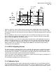
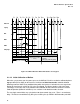
When the core-logic performs a calibration cycle, the following sequence of events occur:
1. The core-logic waits to regain control of the interface. The arbiter will not grant any pending
request from the master until the calibration cycle is completed.
2. Core-Logic asserts GNT and ST[2:0]=110 to indicate start of Calibration Cycle.
3. Both the Graphics chip and the Core-Logic may start their AD group buffer updates -in cycle T2.
AD Strobes and Frame signals must not glitch. The IRDY and TRDY much not glitch or change state until
the respective device signals the end of its update cycle.
4. Core-Logic and Graphics chip must assert IRDY and TRDY respectively to indicate completion of
internal buffer updates. Neither side needs to wait for the other side to give its completion signal.
5. Earliest assertion of IRDY or TRDY is in T3. The latest assertion of IRDY and TRDY are
implementation dependent. However, to minimize any performance impact on other AGP