
Accelerated Graphics Port Interface Specification
AGP3.0 Interface Specification
Rev. 1.0
34
any padding that is necessary. This is the same as AGP2.0 except that the amount of required padding
could be 8, 16, or 24 bytes.
2.3.3 Flow Control
The maximum AGP3.0 data rate (AGP8X) is twice that of AGP2.0. However, the signals that are used
for flow-control by the AGP3.0 Master and Target, as well as the timing relationships, remain the same
as AGP2.0. The primary effect of this change in data rate is in the amount of data buffering required to
support the AGP3.0 Interface.
Use of flow control during AGP transactions is discouraged and should be used only during unusual
circumstances. This implies that a Master should never commit to a read of a given size if there isn’t,
under most circumstances, sufficient buffering available to hold the data, regardless of when it arrives.
Similarly, on a write, the Target should ensure that it does not attempt to fetch the data unless it has the
room to absorb the entire transaction request. A good balance must exist between the number of
requests en-queued, and the buffering available to receive it.
AGP2.0 and AGP3.0 provide two methods for flow-control of the data. The first is used during a data
transfer transaction, while the second is used to stall the start of a new data transaction. For this
discussion these methods are called Block-Level flow-control and Buffer-Full flow-control,
respectively. While these are new terms used for discussion purposes, they do not represent a change
in the flow control mechanisms introduced in AGP.
In addition to the these methods, AGP3.0 continues to support the one cycle Wait State prior to the initial
block of data that can be optionally inserted by the initiator of the data transfer. The timing diagrams
illustrating this can be found in the AGP2.0 Interface Specification.
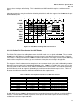
2.3.3.1 Block-Level Flow Control for AGP Reads and Writes
The PCI common clock signals IRDY and TRDY are used for this flow-control. These signals can be
used during AGP read and write transactions initiated by the AGP Master. The AGP Target can also use
this scheme during the data phases of a Fast Write transaction.
The basic scheme allows the receiver of the data to stall the next “block” of data transfer during a read
(receiver is AGP Master) or a write (receiver is core-logic). A “block” consists of four common clock
cycles of data, which is 128 bytes for AGP8X, or twice the size of AGP4X. To stall a block of data, the
receiver must suppress the assertion of TRDY in a pre-defined cycle known as the “throttle point”.
Note: For a description of the throttle point in each transaction, refer to the AGP2.0 Interface
Specification.
Since “Long” transactions are not supported under AGP3.0, the size of a transaction initiated by an
AGP3.0 Master can never exceed 64 bytes. Block-level flow control is not needed for AGP3.0 reads and
writes since no throttle point exists during these transactions.
2.3.3.2 Block-Level Flow Control for Core-logic Fast Writes
The block-level flow-control is still applicable to AGP3.0 Fast Write transactions initiated by the core-
logic. This is because there is no size limit for the data transfer during a Fast Write transaction. As with
AGP2.0, the AGP Master must accept the first block of data transfer. Therefore the AGP Master must