
Accelerated Graphics Port Interface Specification

AGP3.0 Interface Specification
Rev. 1.0
72
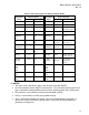
/ NOTES
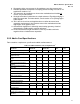
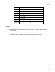
1. All interconnects must be ground referenced.
2. Worst-case interconnect skews listed in this table are based on simulations that take
into account realizable layout topologies and a wide range of interconnect. Trace
lengths include pin-to-trace breakout and trace-to-connector fan-in/-out.
3. Add-in-Card may use stripline or microstrip routing. The routing must be
strongly ground referenced.
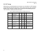
4. This mismatch budget applies to the combined trace lengths of the package
and board signals. Further, note that the set of 16 data signals and the
corresponding strobes, etc. must be routed on the same PCB layer(s).
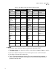
5. Parameter refers to the Space-to-Height ratio of spacing of trace to dielectric
thickness. This requirement must be met to minimize impact of all coupling
effects, including crosstalk. Definitions for microstrip and stripline traces are
provided in the section 3.5.3.1.
6. Propagation delay must account for all such delays up to edge fingers.
7. Effective impedance incorporates all coupling effects including crosstalk as it is
explained in section 3.5.3.1.
8. This represents the contribution to skew on the add-in card and includes all
causes, not just interconnect.
9. Package information is added here for simple reference. Flip-chip packaging is
highly recommended. For further details, consult section 3.7 on package types
in this chapter.
10. Characteristic impedance is defined by trace/stackup geometry, electrical
characteristic of PCB materials and their tolerances.
11. It is very important not to surpass the minimum/maximum interconnect length
specification. Any optimization which exceeds these specified limits could result
in failures. Pin-to-trace breakout length should be as short as possible to
minimize negative effects of reduced trace separation.