
Accelerated Graphics Port Interface Specification
AGP3.0 Interface Specification
Rev. 1.0
74
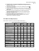
buffer drive characteristics, input signal clamping, and board layout requirements. Note that V
DDQ
is fixed
at 1.5 V for AGP2.0, Universal AGP3.0, and AGP3.0-Only topologies.
In general, the higher transfer rate electrical interface and board requirements are backward compatible
to the lower rates for a particular signaling level. The AGP3.0 interface for a core-logic component on a
universal motherboard must meet all electrical requirements up to its maximum capable transfer rate.
3.5.7 Reset Requirements for AGP3.0 Universal systems
In general, reset requirements have changed very little from those of the AGP interface specification.
Specifically, the only changes have been to require proper management for motherboard/add-in card
interoperability and (for calibration purposes) to formalize the minimum amount of time that must pass
after reset is de-asserted (100 microseconds) before any device can initiate any type of transaction.
AGP3.0-specific system/interface reset requirements are as follows:
• Establish if the interface signaling is to be AGP2.0 or AGP3.0 in universal platforms.
• The signals GC_DET# and MB_DET# should be used to make the necessary determination.
TYPEDET# must also be consistent with these connector signal settings. Decode details are
described in Table 17.
• Both the motherboard and add-in card sides need to establish the interface’s mode of operation.
• If the interface is to be AGP2.0:
− The motherboard (or core-logic component) must force Vrefcg to 750 mV.
− The add-in card (or graphics component) must force Vrefgc to 750 mV.
− The core-logic and graphics components must establish proper drive strengths on their
interface upon exiting reset. Interface ownership is as defined for AGP.
• If the interface is to be AGP3.0:
− The motherboard (or core-logic component) must force Vrefcg to 350 mV.
− The add-in card (or graphics component) must force Vrefgc to 350 mV.
− The core-logic and graphics components must establish proper drive and terminator
strengths on their interface upon exiting reset. Interface ownership is as defined for AGP.
To manage interoperability concerns, the following special cases/steps must be handled.
• When an AGP3.0-only card is plugged into an AGP2.0 slot, it must take the necessary
precautions to protect its electrical interface from damage. In this configuration, the AGP3.0
card must not attempt to respond to any cycle initiated by the motherboard component.
• When an AGP2.0 card is plugged into an AGP3.0-only motherboard, the motherboard must
remove power from V
DDQ
pins. Further activity on the interface should be suspended.
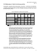
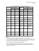
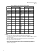
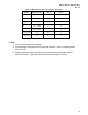
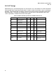
The drive levels for AGP2.0 and AGP3.0 around RESET are given in Table 36 and Table 37. Note that
the correct level must be stable well before the end of RESET. A Universal AGP3.0 design needs to
use the TYPEDET#, GC_DET# and MB_DET# to make the necessary determination of the selected
signaling. The controllers may not detect these signals properly during the power up sequence, so they
must be able to change the signaling on the interface as necessary during RESET.