
Accelerated Graphics Port Interface Specification

AGP3.0 Interface Specification
Rev. 1.0
90
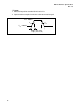
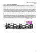
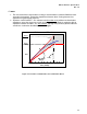
Figure 3-22: V/I Curve for AGP3.0 Transmitter Pull-up
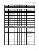
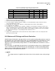
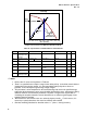
Table 45: Specifications for AGP3.0 Driver and Terminator
/ NOTE
1. Refer to the V/I curves and equations in Table 44.
2. There is no specified curve shape or range for the driver pull-up. It should be sized to drive to
Vswing with a 50 Ω load to ground. It is recommended that the pull-up be as linear as
practical, as this will improve signal timing voltage margins.
3. This parameter is to be interpreted as the cumulative edge rate across the specified range,
rather than the instantaneous rate at any point within the transition range. Adherence to being
within the minimum and maximum parameter is required. Designers are responsible for
simulating the complete network to ensure that there are no adverse signal integrity issues
related to board or package.
4. Mismatched rise and fall slew rates can adversely impact overall t
co
. For this reason, it is
necessary to specify that these slew rates be relatively well matched.
5. Slew rate matching calculated as absolute value of 1 - (slew-r + slew-f)/(2*slew-r).
Symbol
Parameter Condition Min Max Units Notes
ZTarg Target Impedance
for Pull-down and
terminator
45 55 Ω
Iol
Switching Current
Low
0 <Vout<1.0 V Eqt’ns B,C,D Eqt’n A A 1
Ioh
Switching Current
High
Vswing 14.54 17.78 mA 2
Icl Low Clamp Current -3<Vin ≤ -1 -25 + (Vin+1)/0.015 mA
Ich High Clamp Current V
DDQ
+4 > Vin ≥ V
DDQ
+1
25 + (Vin-V
DDQ
-
1)/0.015
mA
slewr
Output Rise Slew
Rate
Vref ± 200 mV 2.0 3.5 V/ns 3
slewr-f
Output Slew Rate
Matching Deviation
Vref ± 200 mV
25 % 4, 5
0.0
0.2
0.4
0.6
0.8
1.0
1.2
1.4
1.6
V
OUT
(Volts)
I
OUT
-
V
Swing
Z
Term
Z
Term
V
Swing
Pull-up
Example
Pull-up V-I
Characteristic