
Audio Codec '97

AC ‘97 Component Specification Revision 2.3 Rev 1.0
11
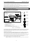
source, or a mix of sources. The optional third PCM ADC is dedicated to voice input, and also extends the range of
acoustic echo cancellation (AEC) capabilities. For details, refer to Section 5.
Consumer equipment (CE) compatible digital output is supported via optional SPDIF_OUT. Modem line 1, optional
modem line 2, and optional handset ADC/DAC pairs shown in the figure describe integration of modem AFE
functionality into the AC '97 architecture. For details, refer to Section 6.
NAMING CONVENTION: Throughout this document signal names have been assigned to be consistent with
the point of view of an application running on the PC.
1.4 Integrating AC ‘97 into the System
Analog sources (legacy)
•CD/DVD: Redbook audio
•VIDEO*: TV tuner
•
A
U
X
*: internal source
A
C ’97
Analog
Codec
CPU
AC-link
PHONE*
MONO_OUT*
Bus sources (digital)
•audio apps
•
games
•digital CD/DVD audio
•
soft MPEG, AC-3, etc
MIC_IN
LINE_OUT
L C R
S
L
S
R
LFE
L R
5.1 channel Digital
(DVD movie
& DVD audio)
CE home theater
via S/PDIF
AUX_OUT
L RC
S S
LINE_IN
Speakerphone I/O
(legacy)
Optional hw acceleration
PCI
bus
AC ‘97
Digital
Controller
SRC*, mix*
3D positional*
wavetable synth*
AC-link
&
control
or 4CH_OUT*
or HP_OUT*
SPDIF_OUT*
L
R
S
L
S
R
4 channel Surround
matrix encoded
(Home Theater)
via line level out
Discrete 4 channel
(3D PC Games)
via
line out + 4CH out
Stereo audio
(w/ 3D positional)
(all PC audio)
via line out
Headset audio
(all PC audio)
via HP out
HP_OUT*
MIC_IN
MIC_IN
LINE_OUT
LINE_OUT
4CH_OUT*
LNLVL_OUT
SPDIF_OUT*
Recommended audio configurations
Motherboard audio (Integrated Controller + AC ’97 Codec)
• “
Basic
” stereo motherboard audio
• “
Deluxe
” 4-channel motherboard audio
• “
Audiophile
” 4-channel with S/PDIF motherboard audio
Riser card (OEM only)
• “
Basic
” stereo audio riser card
• “
Audiophile
” 4-channel with S/PDIF audio riser card
Motherboard + riser card upgrade (OEM only matched Codecs required)
•
“Basic”
stereo motherboard + “
upgrade
” riser card that adds +2-channel with S/PDIF
digital music, MP3
•
d
AC-link
OEM riser slot & card
(optional)
+
+
+
AC ’97
audio
Codec
AC ’97
modem
Codec
LNLVL_OUT
analog mono
analog stereo
optional
*
Key
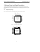
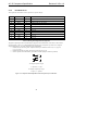
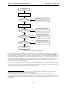
Figure 2. AC ‘97 System Diagram
The system diagram in Figure 2 shows the essential features of a typical AC ‘97 system design. The AC ‘97 Codec
performs DAC and ADC conversions, mixing, and analog I/O for audio (or modem), and always functions as slave
to an AC ‘97 Digital Controller, which is typically either a discrete PCI accelerator or a Controller that comes
integrated within core logic chipsets.
The digital link that connects the AC ‘97 Digital Controller to the AC ‘97 Codec, referred to as AC-link, is a bi-
directional, 5-wire, serial time domain multiplexed (TDM) format interface. AC-link supports connections between
a single Controller and up to 4 CODECs on a circuit board and/or riser card. For details, refer to Section 3.
The system diagram illustrates many of the common PC audio connections, both digital and analog. PC audio today
is rapidly moving towards a
Digital Ready architecture that requires all audio sources must be available in digital
form, but a number of legacy analog sources still require the support of an analog mixing stage.
The AC ‘97 architecture supports a variety of audio output options, including:
• Analog stereo output (LINE_OUT) transmitted to amplified stereo PC speaker array via stereo mini-jack.