
Audio Codec '97

AC ‘97 Component Specification Revision 2.3 Rev 1.0
15
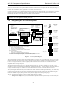
2.3 Signal Descriptions
2.3.1 Power and Ground
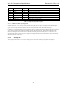
It is recommended that the digital portion (logic and AC-link interface) of AC ‘97 Controllers and Codecs operate at
3.3V (see DC Characteristics in Section 9.1). The analog runs at AVdd = 5V or AVdd = 3.3V.
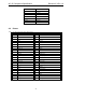
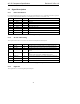
Pin Signal Name Type Description
1 DVdd1 I Digital Vdd (3.3V recommended)
4 Dvss1 I Digital Gnd
7 Dvss2 I Digital Gnd
9 DVdd2 I Digital Vdd (3.3V recommended)
25 AVdd1 I Analog Vdd (5.0V or 3.3V)
26 AVss1 I Analog Gnd
38 AVdd2 I Analog Vdd (5.0V or 3.3V)
42 AVss2 I Analog Gnd
Table 2. Power Signal Descriptions
2.3.2 AC-link and Clocking
These signals connect the AC ‘97 Codec to its Controller counterpart and external crystal.
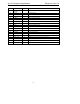
Pin Signal Name Type Description
2 XTL_IN I 24.576 MHz Crystal, 24.576 MHz oscillator or 14.318MHz oscillator input
3 XTL_OUT O 24.576 MHz Crystal if using crystal as clock source (otherwise Reserved)
5 SDATA_OUT I Serial, time division multiplexed, AC ‘97 Codec input stream from the AC ’97
Controller
6 BIT_CLK O
I
Primary Codecs: Master AC-link 12.288 MHz serial data clock output or
input
Secondary Codecs: Slave Codec 12.288 MHz data clock input
8 SDATA_IN O Serial, time division multiplexed, AC ‘97 Codec output stream to the AC ’97
controller
10 SYNC I 48 kHz fixed rate sample sync
11 RESET# I AC ‘97 Master H/W Reset
Table 3. AC-link and Clocking Signal Descriptions
2.3.3 Digital I/O
These signals are AC ‘97 Codec digital inputs and outputs.