
Audio Codec '97

AC ‘97 Component Specification Revision 2.3 Rev 1.0
16
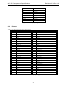
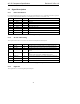
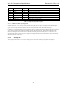
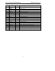
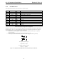
Pin Signal Name Type Description
43 GPIO0 IO Optional Vendor specific GPIO
44 GPIO1 IO Optional Vendor specific GPIO
45 ID0# I Codec ID strap pin (or Generic Cap)
46 ID1# I Codec ID strap pin (or Generic Cap)
47 EAPD O External Amplifier Power Control pin
48 SPDIF_OUT O S/PDIF output (or Vendor specific)
Table 4. Digital I/O Signal Descriptions
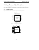
2.3.3.1 S/PDIF transmitter pin assignment
S/PDIF capable AC ‘97 2.3 Codecs in the standard 48-pin QFP must use pin 48 to implement the S/PDIF output
signal. The list of pins that are disabled in the ATE test mode should include the S/PDIF output pin.
In addition, it is suggested that the Codec implement a sensing capability that detects S/PDIF output pin 48 strapped
“high” during power up and disables the S/PDIF capability bit in Register 28h. When disabled, the SPSA and
SPCV bits in Register 2Ah, and all bits in the S/PDIF Control Register 3Ah should return “0” when read. This
optional feature allows system designers to populate or depopulate S/PDIF connector hardware, while maintaining
automatic detection in the driver.
2.3.4 Analog I/O
These signals connect the AC ‘97 Codec to analog sources and sinks, including microphones and speakers.