
Audio Codec '97

AC ‘97 Component Specification Revision 2.3 Rev 1.0
18
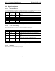
2.3.5 Filter/References
These signals are connected to resistors, capacitors, or specific voltages.
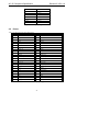
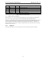
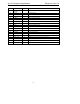
Pin Signal Name Type Description
27 Vref O Reference Voltage
28 Vrefout O Reference Voltage out 5mA drive (intended for mic bias)
29 AFILT1 O Anti-Aliasing Filter Cap - ADC channel
30 AFILT2 O Anti-Aliasing Filter Cap - ADC channel
31 AFILT3 O Anti-Aliasing Filter Cap - optional Mic ADC channel
31 CAP1 O Generic Cap
32 CAP2 O Generic Cap
33 CAP3 O Generic Cap
34 CAP4 O Generic Cap
43 CAP5 O Generic Cap
44 CAP6 O Generic Cap
Table 6. Filtering and Voltage Reference Signal List
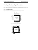
The generic capacitor pins can be used internally to support 3D stereo enhancement, tone control, or other vendor-
specific functions. The AC ‘97 vendor determines the specific use of each capacitor pin. However, to support a
vendor-independent AC ‘97 layout, the following are recommended:
• Internal functions which use generic capacitors between pins should use odd-even (n, n+1) cap pairs,
(1-2, 3-4, 5-6, etc.)
• Internal functions that use generic capacitor to ground may use any cap
• Generic capacitor values should be no greater than 1uF (0805 package or smaller is preferred)
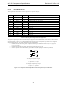
pin
pin
a
b
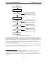
To configure capacitor to gnd:
a = capacitor, b = open
To configure capacitor pin to pin:
a = open, b = capacitor
Figure 5. Example of vendor-independent external capacitor layout connection.