
Audio Codec '97

AC ‘97 Component Specification Revision 2.3 Rev 1.0
21
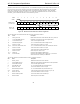
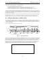
The beginning of all audio sample packets, or Audio Frames, transferred over AC-link is synchronized to the rising
edge of the SYNC signal. SYNC is driven by the Controller. The Controller generates SYNC by dividing
BIT_CLK by 256 and applying some conditioning to tailor its duty cycle. This yields a 48 kHz SYNC signal whose
period defines an audio frame. Data is transitioned on AC-link on every rising edge of BIT_CLK, and subsequently
sampled by the receiving device on the receiving side of AC-link on each immediately following falling edge of
BIT_CLK.
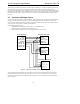
3.3 Controller to Multiple Codecs
Several vendor specific methods of supporting multiple Codec configurations on AC-link have been implemented or
proposed, including Codecs with selective AC-link pass-through and controllers with duplicate AC-links. This
section defines a standard method for implementing configurations that physically separate AC-link functionality
into two or more Codecs, but use a common Digital Controller.
Potential implementations include:
• Multi-channel audio implemented using multiple 2- or 4-channel Codecs
• Separate Codecs for independent audio and modem AFE
• Docking stations, where one Codec is in the laptop and another is in the dock
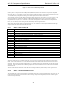
SYNC
BIT_CLK
SDATA_OUT
RESET#
SDATA_IN0
SDATA_IN1
SDATA_IN2
SDATA_IN3
SYNC
BIT_CLK
SDATA_OUT
RESET#
SDATA_IN
AC ‘97 Controller Primary Codec: ID 00
Secondary Codec: ID 01
Secondary Codec: ID 11
SYNC
BIT_CLK
SDATA_OUT
RESET#
SDATA_IN
SYNC
BIT_CLK
SDATA_OUT
RESET#
SDATA_IN
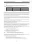
Figure 8. Controller to Multiple Codec connections
This specification defines support for up to four Codecs on the AC-link. By definition there can be one Primary
Codec (ID 00) and up to three Secondary Codecs (IDs 01,10, and 11). The Codec ID functions as a chip select.
Secondary devices therefore have completely orthogonal register sets; each is individually accessible and they do
not share registers.