
Audio Codec '97

AC ‘97 Component Specification Revision 2.3 Rev 1.0
22
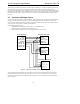
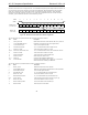
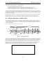
Multiple Codec AC-link implementations must run off a common BIT_CLK. They can potentially save Controller
pins by sharing SYNC, SDATA_OUT, and RESET# from the AC ‘97 Digital Controller. Each device requires its
own SDATA_IN pin back to the Controller. This prevents contention of multiple devices on one serial input line.
Support for multiple Codec operation necessitates a specially designed Controller. An AC ‘97 Digital Controller
that supports multiple Codec configurations implements multiple SDATA_IN inputs, supporting one Primary Codec
and up to three Secondary Codecs.
3.3.1 Primary Codec Addressing
Primary AC ‘97 Codecs respond to register read and write commands directed to Codec ID 00 (see Section 4 for
details of the Primary and Secondary Codec addressing protocols). Primary devices must be configurable (by
hardwiring, strap pin(s), or other methods) as Codec ID 00, and reflect this in the two-bit Codec ID field(s) of the
Extended Audio and/or Extended Modem ID Register(s). See Section 5 for Audio register descriptions and Section
6 for Modem register descriptions.
The Primary Codec may either drive the BIT_CLK signal or consume a signal provided by the digital controller or
other clock generator, as defined in section 3.2 and Figure 7. It is recommended that all AC ‘97 Codecs
configurable as Primary be designed to support at least two (optionally up to four) 50 pF signal loads with 10 k
Ω
input impedance on the BIT_CLK. This ensures that dual (or up to four) Codec implementations will not load down
the clock output.
3.3.2 Secondary Codec Addressing
Secondary AC ‘97 Codecs respond to register read and write commands directed to Codec IDs 01, 10, or 11, see
Section 4 for details of the Primary and Secondary Codec addressing protocols. Secondary devices must be
configurable (via hardwiring, strap pin(s), or other methods) as Codec IDs 01, 10, or 11 in the two-bit field(s) of the
Extended Audio and/or Extended Modem ID Register(s). See Section 5 for Audio register descriptions and Section 6
for Modem register descriptions.
Codecs configured as Secondary must power up with the BIT_CLK pin configured as an input. Using the provided
BIT_CLK signal is necessary to ensure that everything on the AC-link is synchronous. BIT_CLK could also
potentially be used as the clock source (multiplied by 2 so that the internal rate is 24.576 MHz).
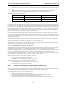
3.3.3 Codec ID Strapping
Audio Codecs in the 48-pin package use pins 45 and 46 (defined as ID0# and ID1#) as strapping (i.e. configuration)
pins to configure the Codec ID. The ID0# and ID1# strapping bits adopt inverted polarity and default to 00 =
Primary (via a weak internal pullup) when left floating. This eliminates the need for external resistors for Codecs
configured as Primary, and maintains backward compatibility with existing layouts that treat pins 45 and 46 as "no
connect" or cap to ground. Pulldowns are typically 0-10 k
Ω and connected to Digital (not Analog) Ground.
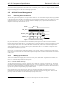
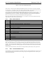
ID1# (pin 46) ID0# (pin 45) Configuration
NC NC Primary ID 00
NC pulldown Secondary ID 01
pulldown NC Secondary ID 10
pulldown pulldown Secondary ID 11
Table 7. Recommended Codec ID strapping