
Audio Codec '97

AC ‘97 Component Specification Revision 2.3 Rev 1.0
24
associated with being dependent on some other Codec’s clock being active. The AC ‘97 Digital Controller could be
designed to manage power to the source of the high-speed clock.
3.5 AC-link Power Management
3.5.1 Powering down the AC-link
The AC-link signals can be placed in a low power mode. When AC ‘97’s Powerdown Register (26h) is programmed
to the appropriate value, both BIT_CLK and SDATA_IN are brought to and held at a logic low voltage level. After
signaling a reset to AC ‘97, the AC ‘97 Controller should not attempt to play or capture audio data until it has
sampled a Codec Ready indication from AC ‘97.
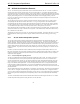
SDATA
_
OUT
TAG
SYNC
BIT
_
CLK
Write to
0x26
Data
PR4
slot 12
prev. frame
TAG
slot 12
prev. frame
SDATA
_
IN
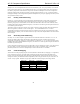
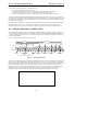
Figure 9. AC-link Powerdown Timing
BIT_CLK and SDATA_IN are transitioned low immediately following decode of the write to the Powerdown
Register (26h) with PR4. When the AC ‘97 Controller driver is at the point where it is ready to program the AC-link
into its low power mode, slots 1 and 2 ARE ASSUMED TO BE the only valid stream in the audio output frame
5
.
After programming the AC ‘97 device to this low power, halted mode, the AC ‘97 Controller is required to drive
and keep SYNC and SDATA_OUT low.
Once the AC ‘97 Codec has been instructed to halt BIT_CLK, a special “wake-up” protocol must be used to bring
the AC-link to the active mode since normal audio output and input frames can not be communicated in the absence
of BIT_CLK.
3.5.2 Waking up the AC-link
There are two methods for bringing the AC-link out of a low power, halted mode. Regardless of the method, it is
the AC ‘97 Controller that performs the wake-up task.
3.5.2.1 Controller Initiates Wake-up
AC-link protocol provides for a “Cold AC ‘97 Reset”, and a “Warm AC ‘97 Reset” (see Section 3.6). The current
powerdown state would ultimately dictate which form of AC ‘97 reset is appropriate. Unless a “cold” or “register”
reset (a write to the Reset Register) is performed, wherein the AC ‘97 registers are initialized to their default values,
registers are required to keep state during all powerdown modes.
Once powered down, re-activation of the AC-link via re-assertion of the SYNC signal must not occur for a
minimum of four audio frame times following the frame in which the powerdown was triggered. When AC-link
powers up it indicates readiness via the Codec Ready bit (input slot 0, bit 15).
5
At this point in time it is assumed that all sources of audio input have also been neutralized.