
Audio Codec '97

AC ‘97 Component Specification Revision 2.3 Rev 1.0
25
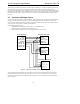
3.5.2.2 Codec Initiates Wake-up
A Codec (running off Vaux) can trigger a wake event (PME#) by transitioning SDATA_IN from low to high and
holding it high until either a warm or cold reset is observed on the AC-link. This functionality is typically
implemented in modem Codecs that detect ring, Caller ID, etc. For details, see Section 7.
Note that when the AC-link is either programmed to the low power mode or shut off completely, BIT_CLK may
stop if the primary codec is supplying the clock, which shuts down the AC-link clock to the Secondary Codec
6
. In
order for a Secondary Codec to react to an external event (phone ringing), it must support an independent clocking
scheme for any PME# associated logic that must be kept alive when the AC-link is down. This includes logic to
asynchronously drive SDATA_IN to a logic high-level which signals a wake request to the AC ‘97 Digital
Controller. For details, see Section 7.
3.6 Codec Reset
There are three types of AC ‘97 reset:
• a cold reset where all AC ‘97 logic (registers included) is initialized to its default state
• a warm reset where the contents of the AC ‘97 register set are left unaltered
• a register reset which only initializes the AC ‘97 registers to their default states
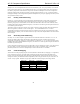
3.6.1 Cold AC ‘97 Reset
A cold reset is achieved by asserting RESET# low for the minimum specified time, then subsequently de-asserting
RESET# high. BIT_CLK and SDATA_IN will be activated, or re-activated as the case may be, and all AC ‘97
control registers will be initialized to their default power on reset values.
RESET# is an asynchronous AC ‘97 input.
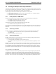
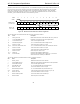
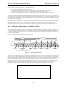
3.6.2 Warm AC ‘97 Reset
A warm AC ‘97 reset will re-activate the AC-link without altering the current AC ‘97 register values. A warm reset
is signaled by driving SYNC high for a minimum of 1
µs in the absence of BIT_CLK.
Within normal audio frames SYNC is a synchronous AC ‘97 input. However, in the absence of BIT_CLK, SYNC is
treated as an asynchronous input used in the generation of a warm reset to AC ‘97.
AC ‘97 MUST NOT respond with the activation of BIT_CLK until SYNC has been sampled low again by AC ‘97.
This will preclude the false detection of a new audio frame.
3.6.3 Register AC ‘97 Reset
All registers in an AC device can be restored to their default values by performing a write (any value) to the Reset
Register, 00h. All registers in an MC device can be restored to their default values by performing a write (any
value) to the extended modem ID Register, 3Ch. For AMC devices the audio and modem registers should be
independently resettable via writes to 00h and 3Ch, respectively.
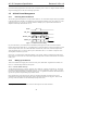
4. AC-link Digital Interface
4.1 Overview
AC-link is the 5 pin digital serial interface that links AC ‘97 Codec to Controller. The AC-link protocol is a bi-
6
Secondary Codec always configures its BIT_CLK pin as an input.