
Audio Codec '97

AC ‘97 Component Specification Revision 2.3 Rev 1.0
26
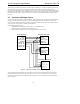
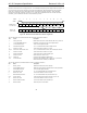
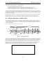
directional, fixed clock rate, serial digital stream. AC-link handles multiple input and output PCM audio streams, as
well as control register accesses employing a time division multiplexed (TDM) scheme that divides each audio
frame into 12 outgoing and 12 incoming data streams, each with 20-bit sample resolution. With a minimum
required DAC and ADC resolution of 16-bits, AC ‘97 could also be implemented with 18 or 20-bit DAC/ADC
resolution, given the headroom that the AC-link architecture provides.
SYNC
Slot #
0 1 2 3 4 5 6 7 8 9
10 11 12
SDATA_OUT
(Controller output)
SDATA_IN
(Codec output)
CMD
ADDR
CMD
DATA
PCM
L FRONT
PCM PCM
CENTER
PCM
L SURR
PCM
R SURR
PCM
LFE
LINE 2
DAC
HSET
DAC
TAG
STATUS
ADDR
STATUS
DATA
PCM
LEFT
PCM
RIGHT
IO
STATUS
RSRVD RSRVD
LINE 2
ADC
HSET
ADC
TAG
IO
CTRL
LINE 1
ADC
SLOTREQ 3-12
RSRVD
LINE 1
DAC
PCM
MIC
PCM L
( n+1)
PCM
R
(n+1)
PCM C
(n+1)
Codec ID
R FRONT
PCM L
( n+1)
PCM R
(n+1)
PCM L
( n+1)
PCM R
(n+1)
Figure 10. Bi-directional AC-link Frame with Slot assignments
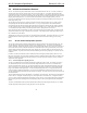
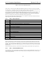
The AC-link output slots (transmitted from the Controller) are defined as follows:
Slot Name Description
0 SDATA_OUT TAG MSBs indicate which slots contain valid data; LSBs convey Codec ID
1 Control CMD ADDR write port Read/write command bit plus 7-bit Codec register address
2 Control DATA write port 16-bit command register write data
3,4 PCM L&R DAC playback 16, 18, or 20-bit PCM data for Left and Right channels
5 Modem Line 1 DAC 16-bit modem data for modem Line 1 output
6,7,8,9 PCM Center, Surround L&R, LFE 16, 18, or 20-bit PCM data for Center, Surround L&R, LFE channels
10 Modem Line 2 DAC 16-bit modem data for modem Line 2 output
11 Modem handset DAC 16-bit modem data for modem Handset output
12 Modem IO control GPIO write port for modem Control
10-11 SPDIF Out Optional AC-link bandwidth for SPDIF output
6-12 Double rate audio Optional AC-link bandwidth for 88.2 or 96 kHz on L, C, R channels.
Actual slots used are controlled by the DRSS bits.
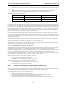
The AC-link input slots (transmitted from the Codec) are defined as follows:
Slot Name Description
0 SDATA_IN TAG MSBs indicate which slots contain valid data
1 STATUS ADDR read port MSBs echo register address; LSBs indicate which slots request data
2 STATUS DATA read port 16-bit command register read data
3,4 PCM L&R ADC record 16, 18 or 20-bit PCM data from Left and Right inputs
5 Modem Line 1 ADC 16-bit modem data from modem Line1 input
6 Dedicated Microphone ADC 16, 18 or 20-bit PCM data from optional 3rd ADC input
7,8,9 Vendor reserved Vendor specific (enhanced input for docking, array mic, etc)
10 Modem Line 2 ADC 16-bit modem data from modem Line 2 input
11 Modem handset input ADC 16-bit modem data for modem Handset input
12 Modem IO status GPIO read port for modem Status