
Audio Codec '97

AC ‘97 Component Specification Revision 2.3 Rev 1.0
27
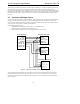
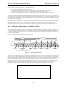
4.2 AC-link Serial Interface Protocol
The AC ‘97 Controller signals synchronization of all AC-link data transactions. The AC ‘97 Codec, Controller, or
external clock source drives the serial bit clock onto AC-link, which the AC ‘97 Controller then qualifies with a
synchronization signal to construct audio frames. SYNC, fixed at 48 kHz, is derived by dividing down the serial bit
clock (BIT_CLK). BIT_CLK, fixed at 12.288 MHz, provides the necessary clocking granularity to support 12 20-bit
outgoing and incoming time slots. AC-link serial data is transitioned on each rising edge of BIT_CLK. The
receiver of AC-link data (Codec for outgoing data and Controller for incoming data) samples each serial bit on the
falling edges of BIT_CLK.
The AC-link protocol provides for a special 16-bit time slot (Slot 0) wherein each bit conveys a valid tag for its
corresponding time slot within the current audio frame. A 1 in a given bit position of slot 0 indicates that the
corresponding time slot within the current audio frame has been assigned to a data stream, and contains valid data.
If a slot is tagged invalid, it is the responsibility of the source of the data, (AC ‘97 Codec for the input stream, AC
‘97 Controller for the output stream), to fill all bit positions with 0’s during that slot’s active time.
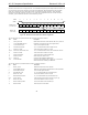
SYNC remains high for a total duration of 16 BIT_CLKs at the beginning of each audio frame. The portion of the
audio frame where SYNC is high is defined as the “Tag Phase”. The remainder of the audio frame where SYNC is
low is defined as the “Data Phase”.
Additionally, for power savings, all clock, sync, and data signals can be halted. This requires that an AC ‘97 Codec
be implemented as a static design to allow its register contents to remain intact when entering a power savings
mode.
4.2.1 AC-link Variable Sample Rate Operation
The AC-link serial interconnect defines a digital data and control pipe between the Controller and the Codec. The
AC-link supports 12 20-bit slots at 48 kHz on SDATA_IN and SDATA_OUT. The time division multiplexed
(TDM) “slot-based” architecture supports a per-slot valid tag infrastructure that the source of each slot’s data sets or
clears to indicate the validity of the slot data within the current audio frame. This tag infrastructure can be used to
support transfers between Controller and Codec at any sample rate. If desired, streams can be sent across the AC-
link in a negotiated, “tag interleaved” fashion, thereby eliminating the need for up-sampling to a common rate such
as 48 kHz.
For audio, AC-link slot interleaved solutions enable the stream of the highest intended quality, either 44.1 or 48
kHz, to be sent along the AC-link with no up-sampling required. Double-rate audio output at 88.2 or 96 kHz is also
feasible by combining two output slots per DAC channel. For modem AFE, data streams at a variety of required
sample rates can be supported.
4.2.1.1 Variable Sample Rate Signaling Protocol
AC-link’s tag infrastructure imposes FIFO requirements on both sides of the AC-link. For example, in passing a
44.1 kHz stream across the AC-link, for every 480 audio output frames that are sent across, 441 of them must
contain valid sample data. Does the AC ‘97 Digital Controller pass all 441 PCM samples followed by 39 invalid
slots? Or does the AC ‘97 Digital Controller evenly interleave valid and non-valid slots? Each possible method
brings with it different FIFO requirements. To achieve interoperability between AC ‘97 Digital Controllers and
Codecs designed by different manufacturers, it is necessary to standardize the scheme for at least one side of the
AC-link so that the FIFO requirements will be common to all designs. The Codec side of the AC-link is the focus of
this standardization.
The new standard approach calls for the addition of “on demand” slot request flags. These flags are passed from the
Codec to the AC ‘97 Digital Controller during every audio input frame. Each time the AC ‘97 Digital Controller
sees one or more of the newly-defined slot request flags set active (low) in a given audio input frame, it knows that it
must pass along the next PCM sample for the corresponding slot(s) in the AC-link output frame that immediately
follows.
The VRA (Variable Rate Audio) bit in the Extended Audio Status and Control Register must be set to 1 to enable
variable sample rate audio operation. Setting the VRA=1 has two functions: