
Audio Codec '97

AC ‘97 Component Specification Revision 2.3 Rev 1.0
28
• enables PCM DAC/ADC conversions at variable sample rates by write enabling Sample Rate Registers 2C-
34h.
• enables the on demand Codec-to-Controller signaling protocol using SLOTREQ bits that becomes
necessary when a DAC’s sample rate varies from the 48 kHz AC-link serial frame rate
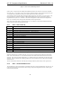
The table below summarizes the behavior:
AC ‘97 functionality VRA=0 VRA=1
SLOTREQ bits Always 0 (data each frame) 0 or 1 (data on demand)
sample rate registers forced to 48 kHz writable
Table 8. VRA Behavior
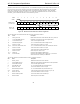
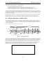
For variable sample rate output, the Codec examines its sample rate control registers, the state of its FIFOs, and the
incoming SDATA_OUT tag bits at the beginning of each AC-link output frame to determine which SLOTREQ bits
to set active (low). SLOTREQ bits asserted during the current AC-link input frame signal which active output slots
require data from the AC ‘97 Digital Controller in the next audio output frame. An active output slot is defined as
any slot supported by the Codec that is not in a power-down state. For fixed 48 kHz operation the SLOTREQ bits
are always set active (low) and a sample is transferred in each frame.
For variable sample rate input, the tag bit for each input slot indicates whether valid data is present or not. Thus,
even in variable sample rate mode, the Codec is always the master: for SDATA_IN (Codec to Controller), the Codec
sets the TAG bit; for SDATA_OUT (Controller to Codec), the Codec sets the SLOTREQ bit and then checks for the
TAG bit in the next frame.
The VRM (Variable Rate Mic Audio) bit in the Extended Audio Status and Control Register controls the optional
MIC ADC input behavior in the same way that VRA=1 controls the PCM ADC.
Note that modem converters (line1, line2, handset) are not affected by the VRA bit, and SLOTREQ bits for active
modem DACs are always treated as valid (data on demand).
4.2.1.2 SLOTREQ Behavior and Power Management
SLOTREQ bits for fixed rate, powered down, and all unsupported Slots should be completed with 0s for maximum
compatibility with the original AC '97 Component Specification. When a DAC channel is powered down, it
disappears completely from the serial frame: output tag and slot are ignored, and the SLOTREQ bit is absent (forced
to zero). The SLOTREQ bit should be forced to 1 in the interval between when the power-down bit for its
associated channel is turned off and when its channel is ready to accept samples. Controllers can take advantage of
this to eliminate the need to poll the AC ‘97, AMC ‘97 or MC ‘97 status registers.
When the Controller wants to power-down a channel, it needs to:
1.
Disable source of DAC samples in Controller
2.
Set PR bit for DAC channel in Registers 26h, 2Ah, or 3Eh
When the Controller wants to power up the channel, it needs to:
1.
Clear PR bit for DAC channel in Registers 26h, 2Ah, or 3Eh
2.
Enable source of DAC samples in Controller
4.2.2 Primary and Secondary Codec Register Addressing
The 2-bit Codec ID field in the LSBs of Output Slot 0 is an addition to the original AC-link protocol that enables an
AC ‘97 Digital Controller to independently access Primary and Secondary Codec registers.
For Primary Codec access, the AC ‘97 Digital Controller:
1.
Sets the AC-link Frame valid bit (Slot 0, bit 15)
2.
Validates the tag bits for Slot 1 and 2 Command Address and Data (Slot 0, bits 14 and 13)
3.
Sets a zero value (00) into the Codec ID field (Slot 0, bits 1 and 0)
4. Transmits the desired Primary Codec Command Address and Command Data in Slots 1 and 2