
Audio Codec '97

AC ‘97 Component Specification Revision 2.3 Rev 1.0
29
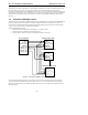
For Secondary Codec access, the AC ‘97 Digital Controller:
1.
Sets the AC-link Frame valid bit (Slot 0, bit 15)
2.
Invalidates the tag bits for Slot 1 and 2 Command Address and Data (Slot 0, bits 14 and 13)
3.
Places a non-zero value (01, 10, or 11) into the Codec ID field (Slot 0, bits 1 and 0)
4.
Transmits the desired Secondary Codec Command Address and Command Data in Slots 1 and 2
Secondary Codecs disregard the Command Address and Command Data (Slot 0, bits 14 and 13) tag bits when they
see a 2-bit Codec ID value (Slot 0, bits 1 and 0) that matches their configuration. In a sense the Secondary Codec ID
field functions as an alternative Valid Command Address (for Secondary reads and writes) and Command Data (for
Secondary writes) tag indicator.
Secondary Codecs must monitor the Frame Valid bit, and ignore the frame (regardless of the state of the Secondary
Codec ID bits) if it is not valid. AC ‘97 Digital Controllers should set the frame valid bit for a frame with a
Secondary register access, even if no other bits in the output tag slot except the Secondary Codec ID bits are set.
4.3 AC-link Output Frame (SDATA_OUT)
The AC-link output frame data streams correspond to the multiplexed bundles of all digital output data targeting AC
‘97’s DAC inputs, and control registers. As mentioned earlier, each AC-link output frame supports up to twelve
(12) 20-bit outgoing data time slots. Slot 0 is a special reserved time slot containing 16-bits which are used for AC-
link protocol infrastructure.
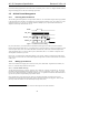
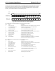
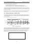
Figure 11 illustrates the time slot based AC-link protocol.
SYNC
BIT_CLK
SDATA_OUT
slot(1)
Time Slot "Valid"
Bits
20.8 µs
(48 kHz)
Slot 1
Slot 2
019 019 0
19 0
Slot 3
Slot 12
81.4 ns
12.288 MHz
slot(2) ID1"0"slot(12)
("1" = time slot contains valid PCM data)
19
Valid
Frame
End of previous
Audio Frame
Tag Phase Data Phase
ID0
Codec ID
Figure 11. AC-link Output Frame
A new AC-link output frame begins with a low to high transition of SYNC. SYNC is synchronous to the rising edge
of BIT_CLK. On the immediately following falling edge of BIT_CLK, the AC ‘97 Codec samples the assertion of
SYNC. This falling edge marks the time when both sides of AC-link are aware of the start of a new audio frame. On
the next rising of BIT_CLK, the AC ‘97 Controller transitions SDATA_OUT into the first bit position of slot 0
(Valid Frame bit). Each new bit position is presented to AC-link on a rising edge of BIT_CLK, and subsequently
sampled by the AC ‘97 Codec on the following falling edge of BIT_CLK. This sequence ensures that data
transitions and subsequent sample points for both incoming and outgoing data streams are time aligned.