
Audio Codec '97

AC ‘97 Component Specification Revision 2.3 Rev 1.0
3
TABLE OF CONTENTS
1. Introduction and Overview.................................................................................................................................9
1.1 AUDIO CODEC FEATURE LIST.........................................................................................................................9
1.2 MODEM CODEC FEATURE LIST.......................................................................................................................9
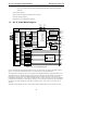
1.3 AC ‘97 CODEC BLOCK DIAGRAM.................................................................................................................10
1.4 INTEGRATING AC ‘97 INTO THE SYSTEM......................................................................................................11
1.5 DRIVER SUPPORT FOR AC ‘97 CONTROLLER/CODEC INTEROPERABILITY ....................................................12
22. Package, Pinout, and Signal Descriptions........................................................................................................13
2.1 48-PIN QFP PACKAGE ...................................................................................................................................13
2.2 PINOUT .........................................................................................................................................................14
2.3 SIGNAL DESCRIPTIONS .................................................................................................................................15
2.3.1 Power and Ground ..............................................................................................................................15
2.3.2 AC-link and Clocking...........................................................................................................................15
2.3.3 Digital I/O............................................................................................................................................15
2.3.3.1 S/PDIF transmitter pin assignment................................................................................................................... 16
2.3.4 Analog I/O ...........................................................................................................................................16
2.3.5 Filter/References..................................................................................................................................18
3. Controller, Codec, and AC-link........................................................................................................................19
3.1 AC-LINK PHYSICAL INTERFACE....................................................................................................................19
3.2 CONTROLLER TO SINGLE CODEC ..................................................................................................................19
3.3 CONTROLLER TO MULTIPLE CODECS ...........................................................................................................21
3.3.1 Primary Codec Addressing..................................................................................................................22
3.3.2 Secondary Codec Addressing ..............................................................................................................22
3.3.3 Codec ID Strapping .............................................................................................................................22
3.4 CLOCKING FOR MULTIPLE CODEC IMPLEMENTATIONS.................................................................................23
3.4.1 Primary AC, MC, or AMC Codec........................................................................................................23
3.4.2 Secondary AC Codec ...........................................................................................................................23
3.4.3 Secondary MC Codec ..........................................................................................................................23
3.4.3.1 Special AC + MC considerations ..................................................................................................................... 23
3.5 AC-LINK POWER MANAGEMENT ..................................................................................................................24
3.5.1 Powering down the AC-link.................................................................................................................24
3.5.2 Waking up the AC-link.........................................................................................................................24
3.5.2.1 Controller Initiates Wake-up............................................................................................................................ 24
3.5.2.2 Codec Initiates Wake-up .................................................................................................................................. 25
3.6 CODEC RESET...............................................................................................................................................25
3.6.1 Cold AC ‘97 Reset ...............................................................................................................................25
3.6.2 Warm AC ‘97 Reset..............................................................................................................................25
3.6.3 Register AC ‘97 Reset..........................................................................................................................25
4. AC-link Digital Interface ..................................................................................................................................25
4.1 OVERVIEW....................................................................................................................................................25
4.2 AC-LINK SERIAL INTERFACE PROTOCOL......................................................................................................27
4.2.1 AC-link Variable Sample Rate Operation............................................................................................27
4.2.1.1 Variable Sample Rate Signaling Protocol ........................................................................................................ 27
4.2.1.2 SLOTREQ Behavior and Power Management................................................................................................. 28
4.2.2 Primary and Secondary Codec Register Addressing ...........................................................................28
4.3 AC-LINK OUTPUT FRAME (SDATA_OUT) ................................................................................................29
4.3.1 Slot 0: TAG / Codec ID.......................................................................................................................30
4.3.2 Slot 1: Command Address Port...........................................................................................................30
4.3.3 Slot 2: Command Data Port ...............................................................................................................31
4.3.4 Slot 3: PCM Playback Left Channel...................................................................................................31
4.3.5 Slot 4: PCM Playback Right Channel.................................................................................................31
4.3.6 Slot 5: Modem Line 1 Output Channel ...............................................................................................31
4.3.7 Slot 6: PCM Center DAC....................................................................................................................31
4.3.8 Slot 7: PCM L Surround DAC (or PCM L n+1).................................................................................32