
Audio Codec '97

AC ‘97 Component Specification Revision 2.3 Rev 1.0
30
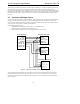
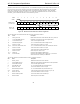
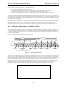
Figure 12. Start of an AC-link Output Frame
SDATA_OUT’s composite stream is MSB justified (MSB first) with all non-valid slots’ bit positions completed
with 0’s by the AC ‘97 Controller. If there are less than 20 valid bits within an assigned and valid time slot, the AC
‘97 Controller always completes all trailing non-valid bit positions of the 20-bit slot with 0’s.
As an example, consider an 8-bit sample stream that is being played out to one of the AC ‘97 Codec’s DACs. The
first 8-bit positions are presented to the DAC (MSB justified) followed by the next 12 bit-positions which are
completed with 0’s by the AC ‘97 Controller. This ensures that regardless of the resolution of the implemented
DAC (16, 18 or 20-bit), no DC biasing will be introduced by the least significant bits.
When mono audio sample streams are output from the AC ‘97 Controller it is necessary that BOTH left and right
sample stream time slots be filled with the same data.
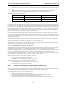
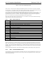
4.3.1 Slot 0: TAG / Codec ID
Bit Description
15 Frame Valid
14 Slot 1 Primary Codec Valid Command Address bit (Primary Codec only)
13 Slot 2 Primary Codec Valid Command Data bit (Primary Codec only)
12 Slot 3: PCM Left channel Valid Data bit
11 Slot 4: PCM Right channel Valid Data bit
10 Slot 5: Modem Line 1 Valid Data bit
9 Slot 6: PCM Center Valid Data bit
8 Slot 7: PCM Left Surround Valid Data bit
7 Slot 8: PCM Right Surround Valid Data bit
6 Slot 9: PCM LFE Valid Data bit
5 Slot 10: Modem Line 2 or PCM Left (n+1) Valid Data bit
4 Slot 11: Modem Handset or PCM Right (n+1) Valid Data bit
3 Slot 12: Modem GPIO or PCM Center (n+1) Valid Data bit
2 Reserved (Set to 0)
1-0 2-bit Codec ID field (00 reserved for Primary; 01, 10, 11 indicate Secondary)
Table 9. Output Slot 0 Bit Definitions
Within slot 0 the first bit is a global bit (SDATA_OUT slot 0, bit 15) which flags the validity for the entire audio
frame. If the “Valid Frame” bit is a 1, this indicates that the current audio frame contains at least one time slot of
valid data. The next 12 bit positions sampled by AC ‘97 indicate which of the corresponding 12 time slots contain
valid data. In this way data streams of differing sample rates can be transmitted across AC-link at its fixed 48 kHz
audio frame rate.
The two LSBs of Slot 0 transmit the Codec ID used to distinguish Primary and Secondary Codec register access.
4.3.2 Slot 1: Command Address Port
The command port is used to control features, and monitor status (see AC-link input frame Slots 1 and 2) for AC ‘97
Codec functions including, but not limited to, mixer settings, and power management (refer to the control register
section of this specification).