
Audio Codec '97

AC ‘97 Component Specification Revision 2.3 Rev 1.0
31
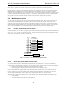
The control interface architecture supports up to sixty-four (64) 16-bit read/write registers, addressable on even byte
boundaries. Only the even registers (00h, 02h, etc.) are currently defined, odd register (01h, 03h, etc.) accesses are
reserved for future expansion.
Note that shadowing of the control register file on the AC ‘97 Controller is an option left open to the implementation
of the AC ‘97 Controller. The AC ‘97 Codec’s control register file is nonetheless required to be readable as well as
writeable to provide more robust testability.
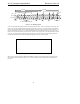
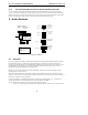
AC-link output frame slot 1 communicates control register address, and write/read command information to the AC
‘97 Codec.
Command Address Port bit assignments:
Bit(19) Read/Write command (1=read, 0=write)
Bit(18:12) Control Register Index (64 16-bit locations, addressed on even byte boundaries)
Bit(11:0) Reserved (Stuffed with 0’s)
The first bit (MSB) sampled by AC ‘97 indicates whether the current control transaction is a read or a write
operation. The following 7 bit positions communicate the targeted control register address. The trailing 12 bit
positions within the slot are reserved and must be completed with 0’s by the AC ‘97 Controller.
4.3.3 Slot 2: Command Data Port
The command data port is used to deliver 16-bit control register write data in the event that the current command
port operation is a write cycle. (as indicated by Slot 1, bit 19)
Bit(19:4) Control Register Write Data (Completed with 0’s if current operation is a read)
Bit(3:0) Reserved (Completed with 0’s)
If the current command port operation is a read, then the entire slot time must be completed with 0’s by the AC ‘97
Controller.
4.3.4 Slot 3: PCM Playback Left Channel
AC-link output frame slot 3 is the composite digital audio left playback stream. In a typical ‘Games Compatible”
PC this slot is composed of standard PCM (.wav) output samples digitally mixed (on the AC ‘97 Controller or host
processor) with music synthesis output samples. If a sample stream of resolution less than 20-bits is transferred, the
AC ‘97 Controller must fill all trailing non-valid bit positions within this time slot with 0’s.
4.3.5 Slot 4: PCM Playback Right Channel
AC-link output frame slot 4 is the composite digital audio right playback stream. In a typical ‘Games Compatible”
PC this slot is composed of standard PCM (.wav) output samples digitally mixed (on the AC ‘97 Controller or host
processor) with music synthesis output samples. If a sample stream of resolution less than 20-bits is transferred, the
AC ‘97 Controller must fill all trailing non-valid bit positions within this time slot with 0’s.
4.3.6 Slot 5: Modem Line 1 Output Channel
AC-link output frame slot 5 contains the MSB justified modem DAC data (if the line Codec is supported). The
optional modem DAC resolution is by default 16-bits. During normal runtime operation the AC ‘97 Controller is
then responsible for completing any non-valid trailing bit positions within this time slot with 0’s.
4.3.7 Slot 6: PCM Center DAC
Slot 6 carries PCM Center data in 6-channel configurations (either single or multiple Codec implementations).