
Audio Codec '97

AC ‘97 Component Specification Revision 2.3 Rev 1.0
32
4.3.8 Slot 7: PCM L Surround DAC (or PCM L n+1)
Slot 7 carries PCM L Surround data in 4- or 6-channel configurations (either single or multiple Codec
implementations). This slot may also contain Double Rate Audio data for PCM L n+1 depending on the
configuration of the DRSS bits in register 20h.
4.3.9 Slot 8: PCM R Surround DAC (or PCM R n+1)
Slot 8 carries PCM R Surround data in 4- or 6-channel configurations (either single or multiple Codec
implementations). This slot may also contain Double Rate Audio data for PCM R n+1 depending on the
configuration of the DRSS bits in register 20h.
4.3.10 Slot 9: PCM LFE DAC
Slot 9 carries PCM LFE data in 6-channel configurations (either single or multiple Codec implementations).
4.3.11 Slot 10: Modem Line 2 Output Channel (or PCM L n+1, or S/PDIF output)
AC-link output frame slot 10 contains the MSB justified modem Line 2 DAC data (or extra bandwidth for Double
Rate Audio PCM Left, or SPDIF output data).
4.3.12 Slot 11: Modem Handset Output Channel (or PCM R n+1, or S/PDIF
output)
AC-link output frame slot 11 contains the MSB justified modem handset DAC data. (or extra bandwidth for Double
Rate Audio PCM Right, or SPDIF output data).
4.3.13 Slot 12: Modem GPIO Control Channel (or PCM C n+1)
AC-link output frame slot 12 contains the modem GPIO control outputs (or extra bandwidth for Double Rate Audio
PCM Center).
4.3.14 Double Rate Audio in Slots 7, 8 or 10-12
Double Rate Audio is intended to provide AC-link bandwidth (headroom) for future higher end audio
implementations where modem is not present. For optional DRA (Double Rate Audio) operation the n+1 sample
output slots 7 and 8 or 10-12 must be employed. Setting the Double Rate Audio (DRA=1) bit in the Extended
Audio Status and Control Register 2Ah indicates that data from PCM L and PCM R in AC-link output slots 3 and 4
is to be used in conjunction with PCM data on additional slots to provide DAC streams at twice the sample rate
designated by the PCM front Sample Rate Control Register 2Ch. The DRSS bits in the General Purpose register
specify the slots for the n+1 sample outputs. PCM L (n+1) and PCM R (n+1) data are by default provided in output
slots 10 and 11. Multichannel Codecs that support PCM Center additionally combine output slots 6 and 12; the
additional Center channel data is not available if the output slots have been set to 7 and 8.
Note that DRA can be used without VRA; in that case the converter rates are forced to 96 kHz if DRA=1.
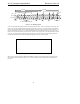
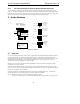
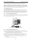
4.4 AC-link Input Frame (SDATA_IN)
The AC-link input frame data streams correspond to the multiplexed bundles of all digital input data targeting the
AC ‘97 Controller. As is the case for audio output frame, each AC-link input frame consists of twelve (12) 20-bit
time slots. Slot 0 is a special reserved time slot containing 16-bits which are used for AC-link protocol
infrastructure.
The following diagram illustrates the time slot-based AC-link protocol.