
Audio Codec '97

AC ‘97 Component Specification Revision 2.3 Rev 1.0
33
SYNC
BIT_CLK
SDATA_IN
slot(1)
Time Slot "Valid"
Bits
20.8 µs
(48 kHz)
Slot 1
Slot 2
019 019 0
19 0
Slot 3
Slot 12
81.4 ns
12.288 MHz
slot(2) "0""0""0"slot(12)
("1" = time slot contains valid PCM data)
19
Codec
Ready
End of previous
Audio Frame
Tag Phase Data Phase
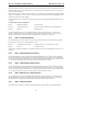
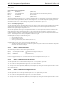
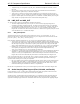
Figure 13. AC-link Input Frame
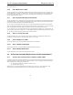
A new AC-link input frame begins with a low to high transition of SYNC. SYNC is synchronous to the rising edge
of BIT_CLK. On the immediately following falling edge of BIT_CLK, the AC ‘97 Codec samples the assertion of
SYNC. This falling edge marks the time when both sides of AC-link are aware of the start of a new audio frame. On
the next rising of BIT_CLK, the AC ‘97 Codec transitions SDATA_IN into the first bit position of slot 0 (“Codec
Ready” bit). Each new bit position is presented to AC-link on a rising edge of BIT_CLK, and subsequently sampled
by the AC ‘97 Controller on the following falling edge of BIT_CLK. This sequence ensures that data transitions
and subsequent sample points for both incoming and outgoing data streams are time aligned.
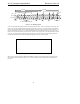
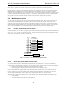
Figure 14. Start of an AC-link Input Frame
SDATA_IN’s composite stream is MSB justified (MSB first) with all non-valid bit positions (for assigned and/or
unassigned time slots) filled with 0’s by the AC ‘97 Codec. SDATA_IN data is sampled on the falling edges of
BIT_CLK.