
Audio Codec '97

AC ‘97 Component Specification Revision 2.3 Rev 1.0
34
4.4.1 Slot 0: TAG
Within slot 0 the first bit is a global bit (SDATA_IN slot 0, bit 15) which flags whether the AC ‘97 Codec is in the
“Codec Ready” state or not. If the “Codec Ready” bit is a 0, this indicates that the AC ‘97 Codec is not ready for
normal operation. This condition is normal following the deassertion of power on reset - for example, while the AC
‘97 Codec’s voltage references settle. When the AC-link “Codec Ready” indicator bit is a ‘1,’ it indicates that the
AC-link and AC ‘97 Codec control and status registers are in a fully operational state. Codec must assert “Codec
Ready” within 400 microseconds after it starts receiving valid SYNC pulses from the controller, to provide
indication of connection to the link and Control/Status registers are available for access. The AC`97 Controller and
related software must wait until all of the lower four bits of the Control/Status Register, 26h, (Section 5.7.11) are set
before attempting any register writes, or attempting to enable any audio stream, to avoid undesirable audio artifacts.
Prior to any attempts at putting an AC ‘97 Codec into operation the AC ‘97 Controller should poll the first bit in the
AC-link input frame (SDATA_IN slot 0, bit 15) for an indication that the Codec is present and ready by checking
for the assertion of the “Codec Ready” bit. Once an AC ‘97 Codec is sampled “Codec Ready”
7
then the next 12 bit
positions sampled by the AC ‘97 Controller indicate which of the corresponding 12 time slots are assigned to input
data streams, and that they contain valid data.
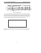
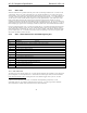
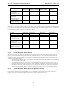
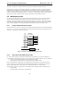
4.4.2 Slot 1: Status Address Port / SLOTREQ signaling bits
Bit Description
19 RESERVED (Set to 0)
18-12 Control Register Index Echo (Set to 0s if tagged “invalid” by AC ‘97 Codec)
11-2 On Demand Data Request Flags (next output frame): 0= send data, 1= do NOT send data
11 Slot 3 request: PCM Left channel
10 Slot 4 request: PCM Right channel
9 Slot 5 request: Modem Line 1
8 Slot 6 request: PCM Center
7 Slot 7 request: PCM Left Surround
6 Slot 8 request: PCM Right Surround
5 Slot 9 request: PCM LFE
4 Slot 10 request: Modem Line 2 or PCM Left (n+1)
3 Slot 11 request: Modem Handset or PCM Right (n+1)
2 Slot 12 request: PCM Center (n+1)
1,0 RESERVED (Set to 0)
Table 10. Input Slot 1 Bit Definitions
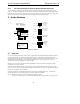
4.4.2.1
Status Address Port
The status port is used to monitor status for AC ‘97 Codec functions including, but not limited to, mixer settings and
power management. AC-link input frame slot 1’s stream echoes the control register index, for historical reference,
for the data to be returned in slot 2 (assuming that slots 1 and 2 had been tagged “valid” by the AC ‘97 Codec
7
There are several subsections within an AC ‘97 Codec that can independently go busy/ready. It is the
responsibility of the AC ’97 controller to probe more deeply into the AC ‘97 Codec’s register file to determine
which subsections are actually ready (refer to Section 6.3 for more information).