
Audio Codec '97

AC ‘97 Component Specification Revision 2.3 Rev 1.0
35
during slot 0.)
Status Address Port bit assignments:
Bit(19) RESERVED (Stuffed with 0)
Bit(18:12) Control Register Index (Echo of register index for which data is being returned)
Bit(11:2) SLOTREQ bits See next section
Bit(1,0) RESERVED (Stuffed with 0’s)
The first bit (MSB) generated by AC ‘97 is always completed with a 0. The following 7 bit positions communicate
the associated control register address, the next 10 bits support AC ‘97’s variable sample rate signaling protocol as
described in Section 4.2.1.1, and the trailing 2 bit positions are filled with 0’s by AC ‘97.
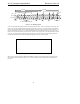
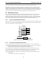
4.4.2.2 SLOTREQ signaling bits
AC-link input frame Slot #1, the Status Address Port, now delivers Codec control register read address and variable
sample rate slot request flags for all output slots. Ten of the formerly reserved least significant bits have been
defined as data request flags for output slots 3-12.
The AC-link input frame Slot 1 tag bit is independent of the bit 11-2 slot request field, and ONLY indicates valid
Status Address Port data (Control Register Index). The Codec should only set SDATA_IN tag bits for Slot 1
(Address) and Slot 2 (Data) to 1 when returning valid data from a previous register read. They should otherwise be
set to 0. SLOTREQ bits have validity independent of the Slot 1 tag bit.
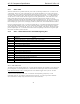
SLOTREQ bits are always 0 in the following cases
• Non-variable rate Codec
• fixed rate mode (VRA=0)
• inactive (powered down) DAC channel (VRA=0 or 1)
SLOTREQ bits are only set to 1 by the Codec in the following case
• Variable rate audio mode (VRA=1) AND active (power ready) DAC AND a non-48 kHz DAC sample rate
and Codec does not need a sample
4.4.3 Slot 2: Status Data Port
The status data port delivers 16-bit control register read data.
Bit(19:4) Control Register Read Data (Completed with 0’s if tagged “invalid” by AC
‘97)
Bit(3:0) RESERVED (Completed with 0’s)
If Slot 2 is tagged invalid by AC ‘97, then the entire slot will be completed with 0’s by AC ‘97.
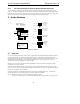
4.4.4 Slot 3: PCM Record Left Channel
AC-link input frame slot 3 is the left channel output of AC ‘97’s input MUX, post-ADC.
AC ‘97’s ADCs can be implemented to support 16, 18, or 20-bit resolution.
AC ‘97 ships out its ADC output data (MSB first), and completes any trailing non-valid bit positions with 0’s to fill
out its 20-bit time slot.
4.4.5 Slot 4: PCM Record Right Channel
AC-link input frame slot 4 is the right channel output of AC ‘97’s input MUX, post-ADC.
AC ‘97’s ADCs can be implemented to support 16, 18, or 20-bit resolution.
AC ‘97 ships out its ADC output data (MSB first), and completes any trailing non-valid bit positions with 0’s to fill