
Audio Codec '97

AC ‘97 Component Specification Revision 2.3 Rev 1.0
36
out its 20-bit time slot.
4.4.6 Slot 5: Modem Line 1 ADC
AC-link input frame slot 5 contains MSB justified, modem ADC output data (if the line Codec is supported). The
optional modem ADC resolution is by default 16-bits. All trailing, non-valid bit positions will be completed with
0’s to fill out its 20-bit time slot. AC ‘97 Controller is then responsible for completing any non-valid trailing bit
positions within this time slot with 0’s.
4.4.7 Slot 6: Dedicated Microphone Record Data
AC-link input frame slot 6 is an optional (post-ADC) third PCM system input channel available for dedicated use by
a desktop microphone. This input channel would supplement a true stereo output which would then enable a more
precise echo cancellation algorithm for speakerphone applications.
AC ‘97’s ADCs can be implemented to support 16, 18, or 20-bit output resolution. Resolution of all PCM input
ADC’s, including this optional Mic ADC is reported by the Reset Register. If supported AC ‘97 will ship out ADC
data of the implemented resolution (MSB first), and fill any trailing non-valid bit positions with 0’s.
AC ‘97 Controller/AC ‘97 pair interoperability can only be guaranteed for non-optional AC ‘97 audio features. An
audio component vendor who develops an AC ‘97 with optional Dedicated Mic channel support should also offer an
AC ‘97 Controller to fully support this feature with a matched set solution.
4.4.8 Slots 7-9: Vendor Reserved
AC-link input frame slots 7-9 are reserved for vendor specific use (docking, expanded input capability, array
microphone, etc) and are otherwise completed with 0’s by the AC ‘97 Codec.
4.4.9 Slot 10: Modem Line 2 ADC
AC-link input frame slot 10 contains the MSB justified modem Line 2 DAC data.
4.4.10 Slot 11: Modem Handset ADC
AC-link input frame slot 11 contains the MSB justified modem Handset DAC data.
4.4.11 Slot 12: Modem GPIO Status
AC-link input frame slot 12 contains the modem GPIO status inputs.
4.5 AC-link Interoperability Requirements and Recommendations
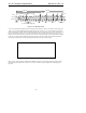
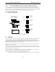
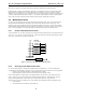
4.5.1 “Atomic slot” Treatment of Slot 1 Address and Slot 2 Data
Command or Status Address and Data cannot be split across multiple AC-link frames. The following transactions
require that valid Slot 1 Address and valid Slot 2 Data be treated as “atomic” (inseparable) with Slot 0 Tag bits for
Address and Data set accordingly (that is, both valid):
• AC ‘97 Digital Controller write commands to Primary Codecs
• AC ‘97 Codec status responses
Whenever the AC ‘97 Digital Controller addresses a Primary Codec or an AC ‘97 Codec responds to a read
command, Slot 0 Tag bits should always be set to indicate actual Slot 1 and Slot 2 data validity.