
Audio Codec '97

AC ‘97 Component Specification Revision 2.3 Rev 1.0
46
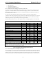
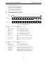
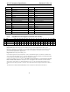
AC-link PCM Audio Data Format
Bit Description
19-4 16-bit sample (MSB bit 19, LSB bit 4)
3-0 Optional: LSBs of 18 or 20-bit sample
Table 14. Audio Slot Data Definitions
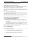
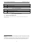
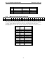
AC-link Audio Interrupt Definition
Bit Description
19-1 Reserved (Audio codec will return zeros in bits 19-1)
10
0 Optional: Assertion = 1 will cause interrupt to be propagated to Audio controller system interrupt. See register 24h
definition for enabling mechanism.
11
Table 15. Audio Interrupt Slot Definitions
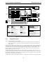
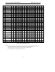
5.7 Baseline Audio Register Set
Table 16 shows the AC ‘97 register indexes and usage. All registers not shown and bits containing an X are
assumed to be reserved.
10
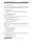
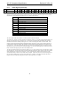
Bits 1-19 of slot 12 is dedicated to modem GPI functionality, and is declared reserved for Audio codecs. Modem
usage of these slots is defined in Table 40. Slot 12-Bit Definitions) and Table 41. Recommended Slot 12 GPIO Bit
Definitions).
11
This functionality is optional for both codec and controllers. Software must ensure that both the controller and
codec are capable of properly handling interrupts. In configurations where no modem capability is present, audio
codecs and software could take advantage of interrupt functionality originally designed for modem features.