
Audio Codec '97

AC ‘97 Component Specification Revision 2.3 Rev 1.0
48
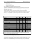
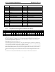
5.7.1 Reset Register (Index 00h)
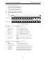
Reg Name D15 D14 D13 D12 D11 D10 D9 D8 D7 D6 D5 D4 D3 D2 D1 D0 Default
00h Reset X SE4 SE3 SE2 SE1 SE0 ID9 ID8 ID7 ID6 ID5 ID4 ID3 ID2 ID1 ID0 na
Reading this register returns the ID code of the part and a code for the type of 3D Stereo Enhancement, if any.
Writing any value to this register performs an audio register reset, which causes all audio registers to revert to their
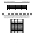
default values. The ID defines the capabilities of AC ‘97 based on the following:
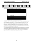
Bit = 1 Function
ID0 Dedicated Mic PCM In channel
ID1 Reserved (was Modem Line Codec support)
ID2 Bass & Treble control
ID3 Simulated Stereo (Mono to Stereo)
ID4 Headphone out support (not LNLVL or 4CH)
ID5 Loudness (bass boost) support
ID6 18 bit DAC resolution
ID7 20 bit DAC resolution
ID8 18 bit ADC resolution
ID9 20 bit ADC resolution
Table 17. Baseline Audio Optional Feature IDs
All DACs operate at the same resolution. All ADCs operate at the same resolution.
The standard AC ‘97 DAC and ADC resolutions are defined as 16-bits. 18- or 20-bit resolution implementations are
optional. The audio driver for an “enhanced” AC ‘97 Controller can determine the implemented DAC and ADC
resolution after it has been loaded by reading the AC ‘97 Codec’s Reset Register which is located at 0x00. If, for
example, the driver has determined that the implemented DAC resolution is 16-bits yet the Controller supports 18-
or 20-bit sample streams for playback, the Controller can either dither the sample streams down to 16-bits or pass
the stream “as is”. Since all AC-link data time slots carry 20 bits, the non-dithered approach will result in the least
significant bits which overrun the DAC width being dropped. For this reason dithering may be an attractive feature
for the Controller that supports greater than 16-bit sample streams.
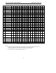
The 3D stereo enhancement decodes are based on Table 18, AC ‘97 48-pin package pinlist. Note that the 3D control
register defines two 16-step controls for the 3D Stereo Enhancement function. These controls can be used to support
center and depth, but can also be used generically. The 3D Control Register should be read to determine if the
selected enhancement is either fixed or variable center and depth. If the lower 8-bits of the 3D Control Register are
non-zero, then the depth/generic1 control is fixed; otherwise it is variable. If the upper 8-bits of the 3D Control
Register are non-zero, then the center/generic2 control is fixed; otherwise it is variable.