
Audio Codec '97

AC ‘97 Component Specification Revision 2.3 Rev 1.0
51
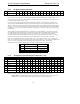
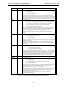
5.7.4 PC Beep Register (Index 0Ah)
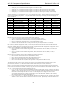
Reg Name D15 D14 D13 D12 D11 D10 D9 D8 D7 D6 D5 D4 D3 D2 D1 D0 Default
0Ah PC Beep Volume Mute X X F7 F6 F5 F4 F3 F2 F1 F0 PV3 PV2 PV1 PV0 X x000h
This controls the level and frequency for the optional PC Beep.
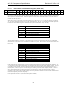
PV3-PV0 controls the volume of the input signal, if implemented, and the generated signal, if implemented. Each
step corresponds to approximately 3 dB of attenuation. The MSB of the register is the mute bit. When this bit is set
to 1 the level for that channel is set at -
∞ dB.
If F7-F0 are writeable, then the optional PCBEEP generation is supported. The beep frequency generated is the
result of dividing the 48kHz48KHz clock by 4 times the number specified in F[7:0], allowing tones from 47 Hz to
12kHz. A value of 00h in bits F[7:0] disables internal PC Beep generation and enables the external PC Beep input if
available. The PV bits control the volume level of the generated signal. The generated signal is not intended to be a
high quality sine wave. The clock output rounded with a capacitor provides sufficient signal quality to provide beep
code signaling.
The PC_BEEP input supports motherboard AC ‘97 Controller /Codec implementations. The intention of routing
PC_BEEP through the Codec analog mixer is to eliminate the requirement for an onboard speaker or piezoelectric
device by ensuring a connection to speakers connected via the output jack. In order for this to be viable the
PC_BEEP signal needs to reach the output jack at all times, with or without the audio driver's support. PC_BEEP
frequency generation supports for motherboard and riser implementations, as no signal needs to be routed.
NOTE: It is recommended that the PC_BEEP be routed to L & R Line outputs even when AC ‘97 is in a RESET
State. This is so that Power On Self Test (POST) codes can be heard by the user in case of a hardware problem with
the PC. This can be accomplished with a high impedance path to the outputs without any attenuation.
The default value can be 0000h or 8000h, which corresponds to 0 dB attenuation with mute off or on.
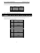
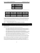
Mute PV3...PV0 Function
0 0000 0 dB Attenuation
0 1111 45 dB Attenuation
1 xxxx ∞ dB Attenuation
Table 21. PC BEEP Volume
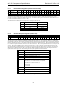
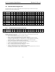
5.7.5 Analog Mixer Input Gain Registers (Index 0Ch - 18h)
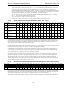
Reg Name D15 D14 D13 D12 D11 D10 D9 D8 D7 D6 D5 D4 D3 D2 D1 D0 Default
0Ch Phone Volume Mute X X X X X X X X X X GN4 GN3 GN2 GN1 GN0 8008h
0Eh Mic Volume Mute X X X X X X X X 20 dB X GN4 GN3 GN2 GN1 GN0 8008h
10h Line In Volume Mute X X GL4 GL3 GL2 GL1 GL0 X X X GR4 GR3 GR2 GR1 GR0 8808h
12h CD Volume Mute X X GL4 GL3 GL2 GL1 GL0 X X X GR4 GR3 GR2 GR1 GR0 8808h
14h Video Volume Mute X X GL4 GL3 GL2 GL1 GL0 X X X GR4 GR3 GR2 GR1 GR0 8808h
16h Aux In Volume Mute X X GL4 GL3 GL2 GL1 GL0 X X X GR4 GR3 GR2 GR1 GR0 8808h
18h PCM Out Volume Mute X X GL4 GL3 GL2 GL1 GL0 X X X GR4 GR3 GR2 GR1 GR0 8808h
This controls the gain/attenuation for each of the analog inputs. Each step corresponds to approximately 1.5 dB. The
MSB of the register is the mute bit. When this bit is set to 1 the level for that channel is set at -
∞ dB.
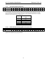
• Register 0Eh (Mic Volume Register) has an extra bit that is for a 20 dB boost. When bit 6 is set to 1 the
20 dB boost is on. The default value is 8008, which corresponds to 0 dB gain with mute on.