
Audio Codec '97

AC ‘97 Component Specification Revision 2.3 Rev 1.0
53
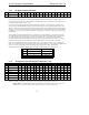
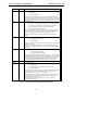
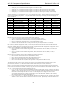
5.7.7 Record Gain Registers (Index 1Ch and 1Eh)
Reg Name D15 D14 D13 D12 D11 D10 D9 D8 D7 D6 D5 D4 D3 D2 D1 D0 Default
1Ch Record Gain Mute X X X GL3 GL2 GL1 GL0 X X X X GR3 GR2 GR1 GR0 8000h
1Eh Record Gain Mic Mute X X X X X X X X X X X GM3 GM2 GM1 GM0 8000h
1Ch is for the stereo input and 1Eh is for the optional dedicated mic channel. Each step corresponds to 1.5 dB.
22.5dB corresponds to 0F0Fh and 000Fh respectively. The MSB of the register is the mute bit. When this bit is set
to 1 the level for that channel(s) is set at -
∞ dB.
The default value is 8000h, which corresponds to 0 dB gain with mute on.
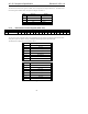
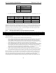
Mute Gx3...Gx0 Function
0 1111 +22.5 dB gain
0 0000 0 dB gain
1 xxxxx −∞ dB gain
Table 24. Record Gain/Attenuation
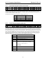
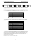
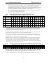
5.7.8 General Purpose Register (Index 20h)
Reg Name D15 D14 D13 D12 D11 D10 D9 D8 D7
D6
D5
D4
D3 D2 D1 D0 Default
20h General Purpose POP ST 3D LD DRSS1 DRSS0 MIX MS LPBK X X X X X X X 0000h
This register is used to control miscellaneous optional functions of the AC ‘97 component. Below is a summary of
each bit and its function. The
POP bit controls the optional PCM out 3D bypass path (the pre- and post-3D PCM out
paths are mutually exclusive). The
MS bit controls the optional microphone selector. The Loudness (bass boost) bit
is to control an optional loudness contour or “bass boost” function. The exact implementation of this is left up to the
vendor. The optional DRSS[1:0] bits control which slots the
n+1 data is present on for Double Rate Audio. This
register should be read before writing to generate a mask for only the bit(s) that need to be changed. The function
default value is 0000h (all bits are off). The optional LPBK bit enables loopback of the ADC output to the DAC
input without involving the AC-link, allowing for full system performance measurements.
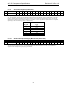
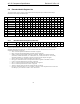
Bit Function
POP PCM out path & mute, 0 = pre 3D, 1 = post 3D
ST Simulated Stereo Enhancement on/off 1 = on
3D 3D Stereo Enhancement on/off 1 = on
LD Loudness (bass boost) on/off 1 = on
DRSS[1:0] Double Rate Slot Select
00: PCM L, R, C n+1 data is on Slots 10-12 (default)
01: PCM L, R n+1 data is on slots 7, 8
10: Reserved
11: Reserved
MIX Mono output select 0=Mix, 1=Mic
MS Mic select 0 = Mic1, 1= Mic2
LPBK ADC/DAC loopback mode
Table 25. General Purpose Bit Definitions