
Audio Codec '97

AC ‘97 Component Specification Revision 2.3 Rev 1.0
55
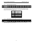
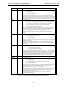
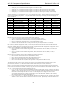
Bit Default Function
I4 0 Interrupt Status (R/W)
0 - Interrupt is clear
1 - Interrupt was generated
Interrupt event is cleared by writing a 1 to this bit. The interrupt bit will change
regardless of condition of interrupt enable (I0) status. An interrupt in the GPI in slot
12 in the AC link will follow this bit change when interrupt enable (I0) is un-masked.
If this bit is set, one or both of I3 or I2 must be set to indicate the interrupt cause.
I[3:2] 00 Interrupt Cause (RO)
I [2]= 0 - Sense status has not changed (did not cause interrupt) (default)
1 - Sense cycle completed or new sense information is available.
I [3]= 0 - GPIO status change did not cause interrupt (default)
1 - GPIO status change caused interrupt.
These bits will indicate the cause(s) of an interrupt. This information should be
used to service the correct interrupting event(s). If the Interrupt Status (bit I4) is
set, one or both of these bits must be set to indicate the interrupt cause.
Hardware must reset these bits back to zero when the Interrupt Status bit is
cleared.
I1 0 Sense Cycle (RW)
0 - Sense cycle not in progress
1 - Sense cycle start
Writing a 1 to this bit causes a sense cycle start if supported. If sense cycle is not
supported this bit is RO.
If a sense cycle is in progress, writing a ‘0’ to this bit will abort the sense cycle.
The data in the sense result register (6Ah) may or may not be valid, as determined
by the IV bit.
I0 0 Interrupt Enable (RW)
0 - Interrupt generation is masked
1 - Interrupt generation is un-masked
S/W should Not un-mask the interrupt unless ensured by the AC ’97 controller that
no conflict is possible with modem slot 12- GPI functionality. AC ’97 2.2 compliant
controllers will not likely support audio codec interrupt infrastructure. In that case,
s/w could poll the interrupt status after initiating a sense cycle and waiting for
Sense Cycle Max Delay to determine if an interrupting event has occurred.
X X Reserved
PG[3:0] 0h Page Selector (RW):
0h - Vendor Specific
1h – Page ID 01(see correspondent definition section 5.8.7)
2h-Fh – Reserved Pages
This register is used to select a descriptor of 16 word pages between registers 60h
to 6Fh. A value of 0h is used to select vendor specific space to maintain
compatibility with AC ’97 2.2 vendor specific registers.
System software can determine implemented pages by writing the page number
and reading the value back. If the value read back does not match the value
written, the page is not implemented.
All implemented pages must be in consecutive. (i.e., page 2h cannot be
implemented without page 1h)
Table 27. Audio Interrupt and Paging Mechanism bits definition