
Audio Codec '97

AC ‘97 Component Specification Revision 2.3 Rev 1.0
56
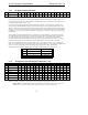
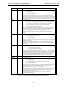
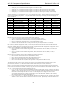
5.7.11 Powerdown Control/Status Register (Index 26h)
Reg Name D15 D14 D13 D12 D11 D10 D9 D8 D7 D6 D5 D4 D3 D2 D1 D0 Default
26h Powerdown Ctrl/Stat EAPD PR6 PR5 PR4 PR3 PR2 PR1 PR0 X X X X REF ANL DAC ADC na
This read/write register is used to program powerdown states and monitor subsystem readiness. The lower half of
this register is read only status, with a 1 indicating that the subsection is “ready”. Ready is defined as the subsection
able to perform in its nominal state. When this register is written the bit values that come in on AC-link will have
no effect on read only bits 0-7.
When the AC-link “Codec Ready” indicator bit (SDATA_IN slot 0, bit 15) is a 1 it indicates that the AC-link and
AC ‘97 Control and Status Registers are in a fully operational state. The AC ‘97 Controller must further probe this
Powerdown Control/Status Register to determine exactly which subsections, if any, are ready.
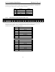
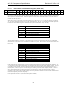
Bit Function
X Reserved
REF Vref’s up to nominal level
ANL Analog mixers, etc. ready
DAC DAC section ready to accept data
ADC ADC section ready to transmit data
Table 28. Baseline Powerdown Status bit Definitions
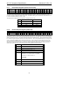
The powerdown modes are as follows. The first three bits are to be used individually rather than in combination
with each other. PR3 can be used in combination with PR2 or by itself. PR0 and PR1 control the PCM ADCs and
DACs only.
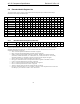
Bit Function
PR0 PCM in ADC’s & Input Mux powerdown
PR1 PCM out DACs powerdown
PR2 Analog Mixer powerdown (Vref still on)
PR3 Analog Mixer powerdown (Vref off)
PR4 Digital Interface (AC-link) powerdown (external clk off)
PR5 Internal Clk disable
PR6 Aux out powerdown
EAPD External Amplifier powerdown
Table 29. Baseline Powerdown Control bit Definitions
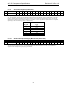
EAPD (formerly PR7) independently controls an output pin that manages an optional external audio amplifier. AC
‘97 compliance requires the implementation of a dedicated output pin for external audio amplifier control. The pin
is controlled via the “EAPD” (External Amplifier Powerdown) bit in Powerdown Ctrl/Stat Register 26h, bit 15
(formerly PR7). EAPD = 0 places a 0 on the output pin, enabling an external audio amplifier, EAPD = 1 shuts it
down. Audio amplifier devices that operate with reverse polarity may require an external inverter. The pin
assignment is pin 47 on the 48-pin QFP package. The list of pins that are disabled in ATE test mode should include
the external amplifier powerdown output pin.
Power-up default is EAPD = 0 (external audio amplifier enabled).