
Audio Codec '97

AC ‘97 Component Specification Revision 2.3 Rev 1.0
58
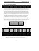
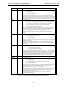
REV1, REV0 AC’97 Revision
00 Revision 2.1 or earlier
01 Revision 2.2
10 Revision 2.3
11 Reserved
Table 31 AC'97 Revision ID
•
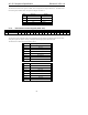
ID1, ID0 is a 2-bit field which indicates the Codec configuration: Primary is 00; Secondary is 01, 10, or 11
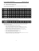
DSA1, DSA0 DACs 1,2 DACs 3,4 DACs 5,6
00 slots 3&4 slots 7&8 slots 6&9
01 7&8 6&9 10&11
10 6&9 10&11 3&4
11 10&11 3&4 7&8
Table 32 Optional DAC Slot duty
If optional Variable Rate Audio is supported by the Codec, the AC ‘97 Controller can further identify the specific
capabilities of each DAC/ADC group by enabling VRA mode (VRA=1 in the Extended Audio Status and Control
Register) and writing and reading values to/from the associated Sample Rate Control Registers (defined below).
The value after cold or register reset for this register is constant, and depends on the features supported and the
hardware configuration as Primary or Secondary Codec.
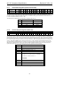
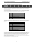
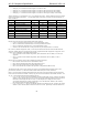
5.8.2 Extended Audio Status and Control Register (Index 2Ah)
Reg Name D15 D14 D13 D12 D11 D10 D9 D8 D7 D6 D5 D4 D3 D2 D1 D0 Default
2Ah Ext’d Audio Stat/Ctrl VCFG PRL PRK PRJ PRI SPCV MADC LDAC SDAC CDAC SPSA1 SPSA0 VRM SPDIF DRA VRA xxxxh
The Extended Audio Status and Control Register is a read/write register that provides status and control of the
extended audio features.
Bits D3-D0 are read/write controls that enable or disable the extended audio features
• VRA=1 enables Variable Rate Audio mode (VRA uses sample rate control Registers 2C-32h). Upon reset,
the audio sample rate registers default to 48 kHz, and VRA=0. When VRA is set to 0 the registers are
forced to BB80h (48 kHz) because that is the only rate supported, and any values previously written to
these registers are lost. Note that modem converters (line1, line2, handset) are not affected by the VRA bit,
and SLOTREQ bits for active modem DACs are always treated as valid (data on demand).
• DRA=1 enables Double-Rate Audio mode in which data from PCM L and PCM R in output slots 3 and 4 is
used in conjunction with PCM L (n+1) and PCM R (n+1) data, to provide DAC streams at twice the sample
rate designated by the PCM Front Sample Rate Control Register. Note that DRA can be used without
VRA; in that case the converter rates are forced to 96 kHz if DRA=1. The slots on which the (n+1) data is
transmitted on is indicated by the DRSS[1:0] bits in the General Purpose register 20h.
• SPDIF=1 enables the S/PDIF transmitter, SPDIF defaults to transmitter subsystem off (powerdown)
• VRM=1 enables Variable Rate Audio mode for the dedicated MIC ADC (VRM uses sample rate Register
34h). VRM controls the optional Mic ADC behavior in the same way that VRA controls the PCM ADC.
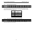
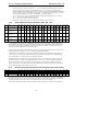
Bits D5-D4, SPSA[1:0], are read/write bits that control the S/PDIF AC-link Slot Assignment. Support for slots
3&4, 7&8, and 6&9 is required, and 10&11 is also recommended. The Controller or driver must perform write
followed by read to determine if support for optional slots 10&11 is implemented. All S/PDIF capable Primary
Codecs must support the following programming assignments, with the default S/PDIF slot assignment
corresponding to the first non-dedicated AC-link slot pair depending on the number of DAC channels supported.