
Audio Codec '97

AC ‘97 Component Specification Revision 2.3 Rev 1.0
59
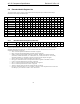
• SPSA[1,0] = 00 S/PDIF source data assigned to AC-link slots 3&4
• SPSA[1,0] = 01 S/PDIF source data assigned to AC-link slots 7&8 [2-ch Primary Codec default]
• SPSA[1,0] = 10 S/PDIF source data assigned to AC-link slots 6&9 [4-ch Primary Codec default]
• SPSA[1,0] = 11 S/PDIF source data assigned to AC-link slots 10&11 [6-ch Primary Codec default]
AMAP compliance is a requirement for AC ’97 2.2 Controllers and Codecs. AMAP compliant Codecs must support
the above programming assignments — only the default SPSA value changes according to Codec ID mapping, as
shown in Table 33:
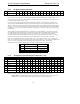
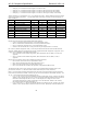
Codec ID Function SPSA = 00 SPSA = 01 SPSA = 10 SPSA = 11
00 2-ch Primary w/ S/PDIF 3&4 7&8 [default] 6&9 10&11
00 4-ch Primary w/ S/PDIF 3&4 7&8 6&9 [default] 10&11
00 6-ch Primary w/ S/PDIF 3&4 7&8 6&9 10&11 [default]
01 +2-ch Secondary w/ S/PDIF 3&4 7&8 6&9 [default]
01 +4-ch Secondary w/ S/PDIF 3&4 7&8 6&9 10&11 [default]
10 +2-ch Secondary w/ S/PDIF 3&4 7&8 6&9 [default]
10 +4-ch Secondary w/ S/PDIF 3&4 7&8 6&9 10&11 [default]
11 +2-ch Secondary w/ S/PDIF 3&4 7&8 6&9 10&11 [default]
Table 33. AC ‘97 2.2 AMAP Compliant Default S/PDIF Slot Assignments
Bits D9-D6 are read only status of the extended audio feature readiness
• CDAC=1 indicates the PCM Center DAC is ready (multichannel Codecs)
• SDAC=1 indicates the PCM Surround DACs are ready (multichannel Codecs)
• LDAC=1 indicates the PCM LFE DAC is ready (multichannel Codecs)
• MADC=1 indicates the MIC ADC is ready (new status for previously-defined AC ‘97 feature)
Bit 10, SPCV, (S/PDIF Configuration Valid), is a read only bit that indicates the status of the S/PDIF transmitter
subsystem, enabling the driver to determine if the currently programmed S/PDIF configuration is supported. SPCV
is always valid, independent of the SPDIF enable bit status.
• SPCV =0 indicates current S/PDIF configuration {SPSA, SPSR, DAC/slot rate, DRS} is not valid (not
supported)
• SPCV =1 indicates current S/PDIF configuration {SPSA, SPSR, DAC/slot rate, DRS} is valid (is
supported)
Bits D14-D11 are read/write controls of the extended audio feature powerdown
• PRI=1 turns the PCM Center DAC off (multichannel Codecs)
• PRJ=1 turns the PCM Surround DACs off (multichannel Codecs)
• PRK=1 turns the PCM LFE DACs off (multichannel Codecs)
• PRL=1 turns the MIC ADC off (MIC ADC operation is independent of PR0 from 26h)
The default value after cold or register reset for this register is all extended features disabled (D3-D0 =0) and
powered down (D14-D11=1). The feature readiness status should always be accurate (D10-D6=x).
Bit D15, VCFG, determines S/P-DIF transmitter behavior when data is not being transmitted. When asserted, this
bit forces the de-assertion of the S/PDIF “Validity” flag, which is bit 28 transmitted in each S/PDIF sub-frame. The
AC ’97 ‘V’ bit is defined in the S/P-DIF Control Register 3Ah.
• If "V" = 0 and “VCFG”=0, then for each S/PDIF sub-frame (Left & Right), bit<28> "Validity” flag reflects
whether or not an internal Codec error has occurred (specifically whether the S/PDIF interface received and
transmitted a valid sample from the AC-Link). If a valid sample (Left or Right) was received and
successfully transmitted, the "Validity” flag should be "0" for that sub-frame. Otherwise, the "Validity”
flag for that sub-frame should be transmitted as "1".
• If “V”=0 and “VCFG” = 1, then for each S/PDIF sub-frame (Left & Right), bit<28> "Validity” flag reflects
whether or not an internal CODEC transmission error has occurred. Specifically an internal CODEC error